38 x-ray tube diagram
The rotating anode X-ray tube is the most common type of X-ray tube found in diagnostic imaging departments. The reason for this is that it is able to produce higher intensities of X-rays than the stationary anode tube. This is due to two factors: 1. The heat deposited in the anode during an X-ray exposure is spread over a larger area and so ... This is an online quiz called xray tube. There is a printable worksheet available for download here so you can take the quiz with pen and paper. Your Skills & Rank. Total Points. 0. Get started! Today's Rank--0. Today 's Points. One of us! Game Points. 10. You need to get 100% to score the 10 points available.
Internal parts: Cathode Anode. 11. Cathode: Cathode is the negative side of the X-ray tube and consists of the following two parts: 1-Filament 2-Focusing cup. 12. 1- Filament : Filament is a coil of wire usually 2 mm in diameter and 1 or 2 cm long. The filaments are made of tungsten. Filaments must be able to: - Boil off electrons (thermionic ...
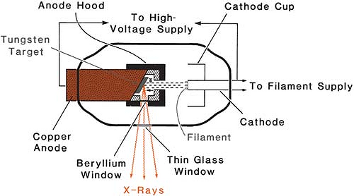
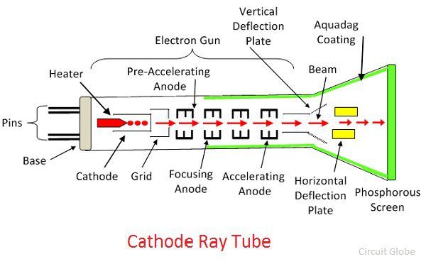
X-ray tube diagram
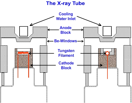
Condensation on Be window will cause window corrosion, vacuum loss and X-ray tube failure Radiation Shielded X-ray Tube Jupiter 5000 Series Technical Datasheet The Jupiter 5000 Series is a 50kV, 50W packaged X-ray tube designed for applications where high flux density and continuous operation are important. Figure 2-1 (a). Schematic diagram of x-ray tube and circuit V f X-ray tube current • Electron cloud near the filament creates space charge region, opposing the release of additional electrons • Increase in tube voltage increases tube current; limited by filament emission • High filament currents and tube voltage of 40 to 140kV must be used By contrast, maintaining a constant x-ray tube voltage with an increase in magnification of x 2.5 would have required an increase in entrance skin air kerma (and power loading to the x-ray tube anode) of 625% (i.e., 2.5^2) because of the six fold reduction in exposed area of the input phosphor.
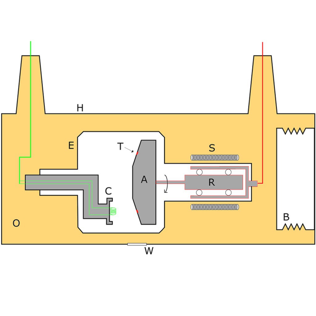
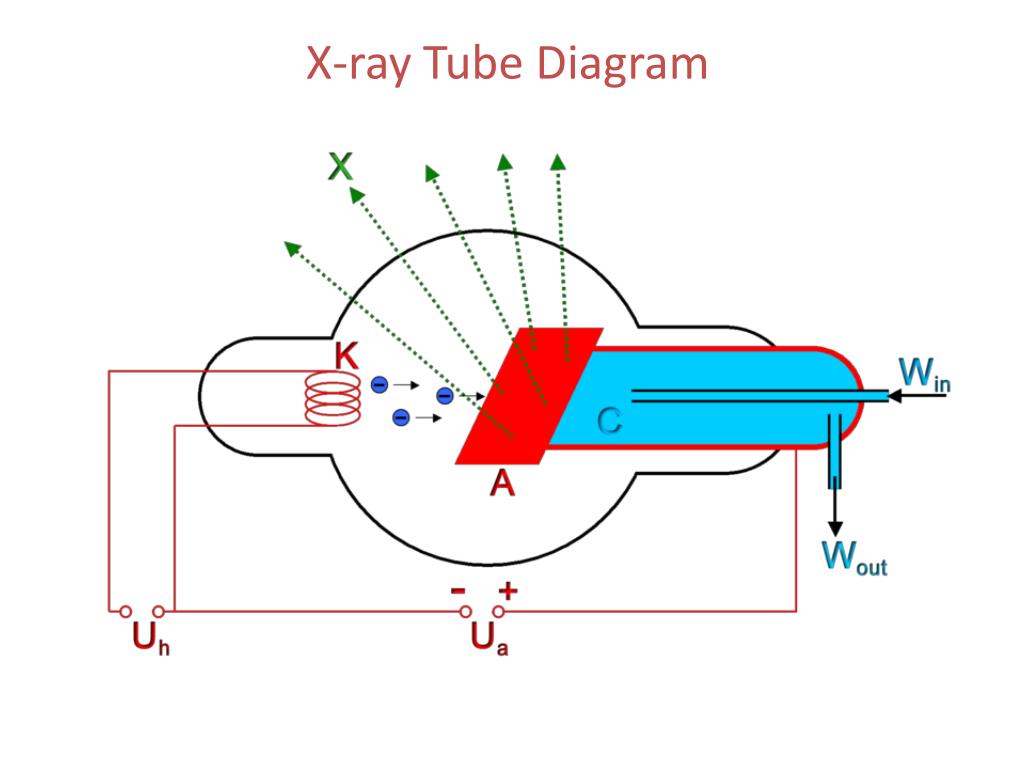
X-ray tube diagram. Reload page. Diagrammatic representation of an X-ray tube: A: anode. B: expansion bellows (provide space for oil to expand) C: cathode (and heating-coil) E: tube envelope (evacuated) H: tube housing. O: cooling dielectric oil. X-ray Tube. X-ray tube should be focal spot 0.6 mm small, 1.0 mm or similar large. Stipulate the heat unit and anode storage capacity. Stipulate the X-ray tube heat unit storage capacity. X-ray tube should have high-speed rotor circuitry. X-ray collimator must be of high quality to minimize radiation outside the selected field of radiation. It surrounds the filament to condense the electrons into a beam of electrons that can be accelerated toward the anode. Without the focusing cup, there is a spread of electrons (caused by electrostatic repulsion) that minimise the efficiency of the x-ray tube because not all the x-rays produced will be emitted. An X-ray source is a vacuum tube that produces X-rays, also called an X-ray tube. To generate X-rays, a current is first passed through the filament to heat it. The filament generates hot electrons, which are accelerated by high voltage and collide with the target of the anode. The energy of the X-rays is proportional to the tube current of the ...
5.3 X-RAY TUBES 5.3.1 Components of the X Ray Tube The production of both Bremsstrahlungand Characteristic Radiationrequires energetic electrons hitting a target Principle components of an X ray tube are an Electron Source from a heated tungsten filament with a focusing cup serving as the tube Cathode, an Anode or Target and a X Ray Tube Diagram Labeled. New- Pleasant to our weblog, in this particular time We'll show you about x ray tube diagram labeled. . And now, this can be a primary image: Sortech LS OD 50 03N X Ray Sorter from x ray tube diagram labeled , source:sortech.co.za. Sortech LS OD 6 X Ray Sorter from x ray tube diagram labeled , source:sortech.co.za. An X-ray tube is a vacuum tube that converts electrical input power into X-rays. The availability of this controllable source of X-rays created the field of radiography, the imaging of partly opaque objects with penetrating radiation.In contrast to other sources of ionizing radiation, X-rays are only produced as long as the X-ray tube is energized.X-ray tubes are also used in CT scanners ... The X-ray spectrum. As a result of characteristic and bremsstrahlung radiation generation a spectrum of X-ray energy is produced within the X-ray beam. This spectrum can be manipulated by changing the X-ray tube current or voltage settings, or by adding filters to select out low energy X-rays.
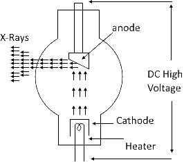
As the DC voltage (anode-to-cathode of the x-rays tube) is increased, the wavelength of x-rays decreases. Same tubes now operate at more than a million volts. Block Diagram of X-Rays machine. Figure 2: Block Diagram of X-Ray Operation/Working of X-Ray Machine High voltage source and high voltage transformer The x-ray tube working principle and diagram is shown below. Generation of X-rays in X-ray tubes. An X-ray generator is a device used to generate X-rays .An X-ray imaging system consists of an X-ray source or generator (X-ray tube) and an image detection system. The X-ray tube X-ray tube diagrams. Case contributed by Dr Matt Skalski . Diagnosis not applicable. Diagnosis not applicable. From the case: X-ray tube diagrams. Start studying X-Ray physics Chapter 6: The X-ray Tube, (X-Ray Tube Diagram). Learn vocabulary, terms, and more with flashcards, games, and other study tools.
Introduction. Chapter 1 provided a general discussion of the x-ray tube head assembly and the function of the major parts of the design. Chapter 4 discussed the components of the x-ray circuit and the events that lead to the production of x-rays in the x-ray tube. This chapter examines the x-ray tube itself (), its general construction, and how it works.

125th Anniversary Of X Rays Part 2 X Ray Tube Developments Metrology And Quality News Online Magazine
The anode is the positive end of the tube rotating using an induction motor. It provides the target for electron interaction to produce x-rays. It serves as an electrical and thermal conductor
1.0 X-RAY TUBE Attached to a tube support. Produces X-rays (& Heat). Operated at high voltage (40 - 150 kVp). Insulation required. Oil used to cool X-ray tube during exposures. Oil also acts as an insulator. X-ray tube lead lined. Incorporate safety interlocks. Light Beam Diaphragm. Integrated Collimation.
X-rays. In 1895 Roentgen was working with discharge tubes when he discovered that photographic plates . A diagram of a modern X-ray tube is shown below. X-ray tubes evolved from experimental Crookes tubes with which X-rays were first . Diagram of continuum and characteristic lines; ^ John G. Stears, Joel P.
X-ray Tube characteristics: Using of single exp. chart Fine focus and Large focus effects X-ray image resolution depends on the size of the X-ray tube focal spot (effective focus) Fine (~ 0.5mm) or Broad (~1mm) The BF smears the contours of the imaged objects (this increases with the increase of object-to-film distance) Focus Object Film
After a few failed attempts, I managed to get my xray tube rotor spinning. Basically the motor is a 3 phase set-up, however one particular wiring diagram all...
the picture, you can see the technologist handling the x-ray tube. She is manipulating the field size by adjusting a device called the "collimator" which is attached to the x-ray tube housing. The rectangular looking device just above the collimator is the housing for the x-ray tube. The diagram on the right shows the x-ray tube by itself .
Dental X-ray Tube Head Diagram. The following frames will show a diagram of the dental x-ray tubehead. A tubehead part name and its definition will appear on the screen. Click on the part name. Dental X-ray Tube Head Diagram. The tubehead is a sealed, heavy metal housing that contains the x-ray tube that produces dental x-rays.
potential of the x-ray tube, or the kilovoltage that will be flowing through the tube once the exposure is made. Next is the exposure switch, or the timing circuit, which is used to complete the x-ray exposure. It regulates the length of the exposure, and it's where the tech starts and the .
THE X-RAY TUBE. X-rays are generated in an x-ray tube. The purpose of the x-ray tube is to produce a controlled x-ray beam. The tube must be responsive to manual control so that both the amount and the penetrating power of the radiation produced are accurately controlled.
The x-ray tube working principle and diagram is shown below. Generation of X-rays in X-ray tubes. An X-ray generator is a device used to generate X-rays .An X-ray imaging system consists of an X-ray source or generator (X-ray tube) and an image detection system. The X-ray tube (high vacuum diode) operates by emitting electrons from a heated ...
By contrast, maintaining a constant x-ray tube voltage with an increase in magnification of x 2.5 would have required an increase in entrance skin air kerma (and power loading to the x-ray tube anode) of 625% (i.e., 2.5^2) because of the six fold reduction in exposed area of the input phosphor.
Figure 2-1 (a). Schematic diagram of x-ray tube and circuit V f X-ray tube current • Electron cloud near the filament creates space charge region, opposing the release of additional electrons • Increase in tube voltage increases tube current; limited by filament emission • High filament currents and tube voltage of 40 to 140kV must be used
Condensation on Be window will cause window corrosion, vacuum loss and X-ray tube failure Radiation Shielded X-ray Tube Jupiter 5000 Series Technical Datasheet The Jupiter 5000 Series is a 50kV, 50W packaged X-ray tube designed for applications where high flux density and continuous operation are important.








0 Response to "38 x-ray tube diagram"
Post a Comment