39 ramps 1.6 wiring diagram
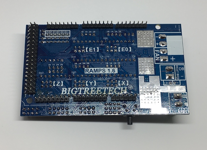
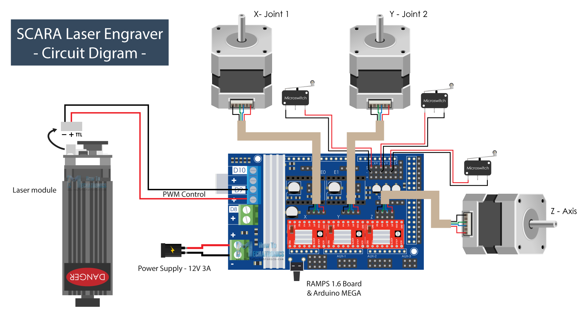
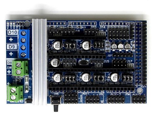
Ramps Shield V1.6. The RAMPS 1.6 is the second RAMPS iteration released by BIQU/BIGTREETECH. It replaces the original green power connector with a pair of screw terminals, adds a larger heatsink over the MOSFETS, and has a larger bed MOSFET. It maintains the surface-mounted fuses and flush MOSFETS of the RAMPS 1.5. Ramps 1 6 Wiring Diagram. Ramps shield v1 6 micro robotics twinteeth wiring the electronics 1 4 with stepper motors arduino old for y axis robo reprap ramps1 printer circuit how to wire a x by morganlowe chinese hardware plus datasheet. Wiring Of Electronic Components To Ramps 1 4 Arduino Shield Scientific Diagram.
RAMPS 1.6 Plus Datasheet Introduction: 1.BIGTREETECH Ramps 1.6 plus is mainly a new adapter ramps board for the upgrade of the old Ramps 1.6 driver using the SPI working mode wiring complex problem. 2.The BIGTREETECH Ramps 1.6 plus uses the SPI mode of operation, which can be achieved simply by plugging and unplugging the jumper cap.
Ramps 1.6 wiring diagram
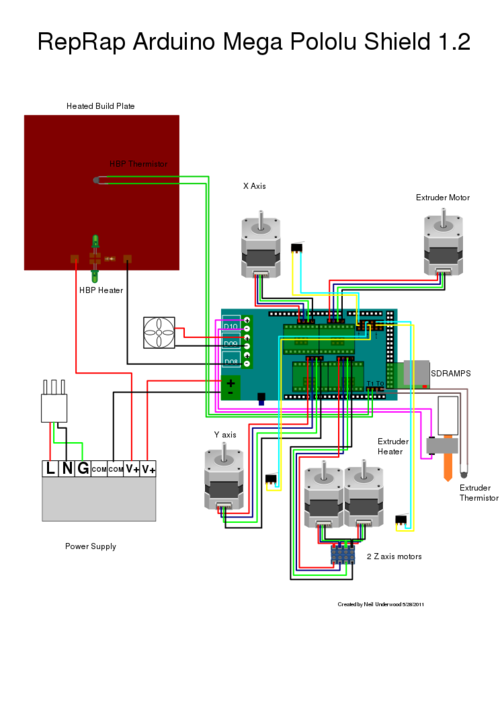
Ramps 1.4 Stack¶ If you bought this from V1 Engineering then this has already been done for you just plug in the steppers and go. Ramps 1.4 - Any control board can be used to control the Mostly Printed CNC, Here is how to set up a ramps stack. (the last post seems to have disappeared so I am re-posting this) I don't know if this really counts as hardware development for the MP3DP, but as the ramps 1.4 was dropped from the store not that long ago, and I am a ramps runner I thought these looked interesting. So I am running ramps on my new MP3DP I made. I was using a relay, and I have had to run my anet a8 bed through a relay as well ... New update: RAMPS 1.5 Board RepRap Arduino Mega Pololu Shield which improve the heatbed wattage to 110W and a total watts about 200W. RepRap Arduino Mega Pololu Shield versions RAMPS 1.5 wiring diagram
Ramps 1.6 wiring diagram. This "RAMPS 1.6" is designed for use with TMC drivers which have a serial (SPI) interface and this interface uses the pins that are reset/sleep on the A4988. On the A4988 these pins need to be pulled low (connected to GND) to enable the chip. I'm guessing one of the two is already connected to ground (because it's not used on the TMC drivers at ... Ramps 1.6 Wiring Diagram from preview.redd.it. To properly read a electrical wiring diagram, one offers to know how the components in the system operate. For example , in case a module is powered up and it sends out the signal of half the voltage and the technician does not know this, he'd think he has a problem, as this individual would expect ... The RAMPS 1.6 has only 1 pair of power inputs. Which pair from the PSU do I connect to the board? Or do I combine them and connect them to their polarity respectively? I have a cooling fan (12 V) for part cooling. In RAMPS 1.4, I had it connected to the pins between the power inputs and the X stepper driver on the board. - all the ramps not to be more than 3% when straight and 2.5% when curved ... (I have 2 lengths: full main line train 1.6 m and secondary train .5 m ... Forum » General topics » Digital » Wiring diagram.
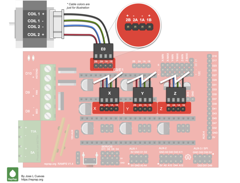
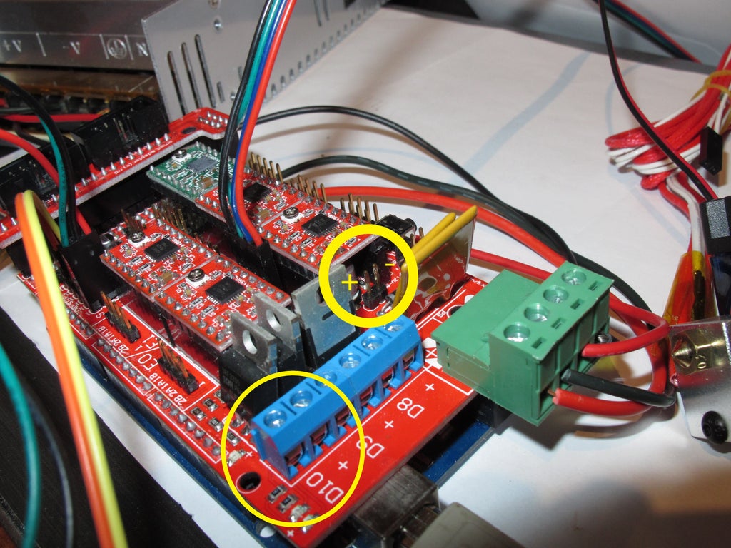
13:20 Connect the RAMPS board to the Taurino. 13:30 I had to remove the DC jack plug from the Taurino so the RAMPS board would sit correctly. 15:06 Plug in the terminal plug into the RAMPS board, turn the ATX power supply on, and check that the LED on the Taurino lights up (and beware of the magic smoke..!). Wiring 3D Printer RAMPS 1.4: I've had some requests about how to wire a 3D Printer and more specifically, how I wired my Laminated Prusa I3 printer.In this instructable I will walk through all the components and steps required to setup a 3D Printer using the most commonly used … Take the Ramps board and solder two male pins on the 12V-Aux pin holes (see next picture) Most Ramps boards come without these pins. Later we will connect there the cooling fan (see wiring diagram below). Check that all the microstep jumpers are installed in all axes. TwinTeeth uses 1/16 microstepping. Install the Ramps on the Arduino. The RAMPS 1.4 offers no pull-up circuits, current limiting resistors or other protections. Wiring improperly an endstop that uses 5V may damage an IO port on the ATmega 2560 or the Arduino itself, this is a particular issue with clones of the Arduino ATmega2560.
Mega2560+ramps 1.4 kit, The GT2560 can not only take full place the them on respect of both software and hardware, but also features compact size, more convenient connection, and more stable. 2. Adopt ATmega2560 as the main control chip, coupled with the high-performance USB serial converter CH340C. 3. The drawback of RAMPS 1.5 and 1.6 are that they use SMD polyfuses which are a little more difficult to replace (for some people) than the large fuses from the RAMPS 1.4. However, the fuses of the RAMPS 1.4 are sticking out, then tend to bend once in a while when you work on the board and could therefore become prone to metal fatigue and break. I ordered a RAMPS 1.6+ thinking higher is better, turns out the ramps 1.6+ is made for a TMC2130. Now I did get two TMC2130's, but i also got two DRV8825's for the Z and extruder. Anyway, that means that how to set it up is different than a regular ramps 1.4, meaning that you need to adjust a few things if you are using a A4498 or a DRV8825. RAMPS1.4 + ATX power Wiring In this case, 12V from ATX Power is supplied to 1117 regulator on Arduino through diode D1 on RAMPS1.4. The 1117 series Voltage Regulator in Arduino can operate with up to 20 V input. Therefore Arduino can work well without USB. (Standalone with an SD card)
Ramps 1.6 Wiring Diagram. To properly read a cabling diagram, one has to learn how typically the components in the program operate. For example , in case a module will be powered up also it sends out the signal of 50 percent the voltage and the technician would not know this, he'd think he provides a problem, as this individual would expect a ...
Ramps is short for reprap Arduino mega pololu shield, it is mainly designed for the purpose of using pololu stepper driven board (similar to 4988 driven board). Ramps can only work when connected to its mother board Mega 2560 and 4988/DRV8825. Owning to its stability in operation and great compatibility with most 3Dprinter (all reprap-model
Ramps 1 6 Wiring Diagram. By Margaret Byrd | October 31, 2018. 0 Comment. Twinteeth wiring the electronics diyouware com ramps 1 4 with 6 stepper motors project guidance arduino forum of electronic components to shield scientific diagram reprap ramps1 printer circuit connection graph osoyoo ks0091 keyestudio kit mega 2560 5x a4988 lcd 2004 ...
Download files and build them with your 3D printer, laser cutter, or CNC. Thingiverse is a universe of things.
This is a simple tutorial on how to install either or both A4988 or DRV8825 on the RAMPS 1.6 and configure the Marlin firmware for 2.0.x.One Time Tips, You C...

Witbot Ramps 1 6 Plus Open Source Expansion Control Board Upgraded Ramps 1 5 1 6 Support Tmc2130 2208 St820 A4988 Driver For 3d Printer Buy Online In Qatar At Qatar Desertcart Com Productid 91593041
RAMPS 1.4 is probably the most widely used electronics for RepRap machines as of March 2014. It consists of a RAMPS 1.4 shield, an Arduino Mega 2560 board (or a clone), and a max of five Pololu Stepper drivers. It can control up to 5 stepper motors with 1/16 stepping
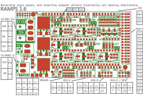
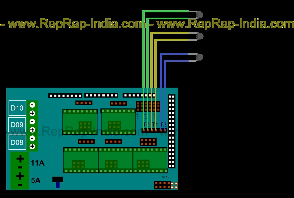
The markings on the diagram 11A and 5A, refer to the number of amps or current each set of components require. The 11A terminal is used to power a heated build platform, and the 5A terminal is used to power the RAMPS board, stepper motors and extruder.
But there are some difference, one lies in the configuration of I/O pins.Ramps 1 4 Fan Wiring Diagram - For information purpose here is the official schematic of the Ramps board. It is the same you will find on the official reprap wiki. This schematic give you more data on all the pin out and also on the optional headers.
04:19:00 - 05:26:00 - Ramps installation onto Mega 2560 board 05:26:00 - 08:02:00 - Limit Switch wiring installation 08:02:00 - 10:15:00 - Stepper Motor wiring installation 10:15:00 - 12:25:00 - Control Screen wiring installation Please see written instructions below for greater detail and additional information.
Wiring Diagram and Schematic Role. Ramps Wiring Diagram . September 10, 2018 1 Ks0091 Keyestudio Printer Kit Ramps 1 4 Mega 2560 5x A4988 Lcd 2004 Smart Controller Wik Found 9732 libraries which are related to ramps schematic RAMPS1.4. RAMPS_dossier.pdf - Free download as PDF File (.pdf), Text File (.txt) or read online for free
The RAMPS 1.6 is the second RAMPS iteration released by BIGTREETECH. It replaces the original green power connector with a pair of screw terminals, adds a larger heatsink over the MOSFETS, and has a larger bed MOSFET. It maintains the surface-mounted fuses and flush MOSFETS of the RAMPS 1.5. - ramps-1.6/R6Schematic diagram.pdf at master · bigtreetech/ramps-1.6
New update: RAMPS 1.5 Board RepRap Arduino Mega Pololu Shield which improve the heatbed wattage to 110W and a total watts about 200W. RepRap Arduino Mega Pololu Shield versions RAMPS 1.5 wiring diagram
(the last post seems to have disappeared so I am re-posting this) I don't know if this really counts as hardware development for the MP3DP, but as the ramps 1.4 was dropped from the store not that long ago, and I am a ramps runner I thought these looked interesting. So I am running ramps on my new MP3DP I made. I was using a relay, and I have had to run my anet a8 bed through a relay as well ...
Ramps 1.4 Stack¶ If you bought this from V1 Engineering then this has already been done for you just plug in the steppers and go. Ramps 1.4 - Any control board can be used to control the Mostly Printed CNC, Here is how to set up a ramps stack.

Enable Auto Leveling For Your 3d Printer With An Inductive Sensor Marlin Firmware 3 Steps With Pictures Instructables
Ramps 1 6 Panel Kontrol Ekspansi Dengan Heatsink Ramps 1 4 1 5 Untuk Arduino 3d Printer Board Shopee Indonesia
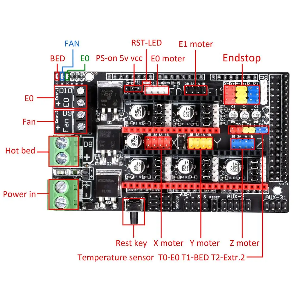
Ramps 1 6 Plus Upgrade Ramps 1 6 1 5 1 4 Control Board Support A4988 Drv8825 Tmc2208 Tmc2130 Driver 4 Layer 3d Printer Parts 3d Printer Parts Accessories Aliexpress











0 Response to "39 ramps 1.6 wiring diagram"
Post a Comment