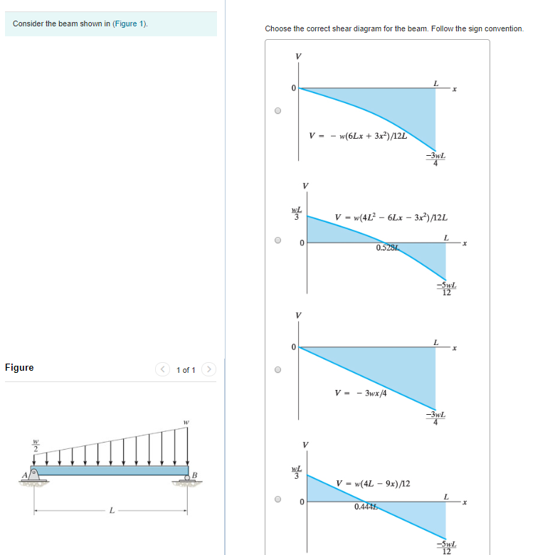
39 select the correct shear diagram for the beam. (figure 1)
Figure 1 part a. Select the correct shear diagram for the beam figure 1. A beam is shown in the figure below. Figure 1 select the correct shear diagram for the beam. Note make sure you place only one vertical line at places that require a vertical line. Draw the shear diagram for the beam. Follow the sign convention. For The Beam And Loading Shown A Select Correct Shear Bending Moment Diagrams B Determine Equations Of Curves Study. Problem 9 1 Two Beam Segments Ac And Cd Are Connected Together At C By A Frictionless Pin Segment Is Cantilevered From R. 329 6 1 Draw The Shear And Moment Diagrams For Shaft Bearings At A B Exert Only Vertical Reactions On.
A beam is shown in the figure below. (Figure 1) Part A : Draw the shear diagram for the beam. Note - Make sure you place only one vertical line at places that require a vertical line. If you inadvertently place two vertical lines at the same place, it will appear visually correct because the lines overlap, but the system will mark it wrong. Part B

Select the correct shear diagram for the beam. (figure 1)
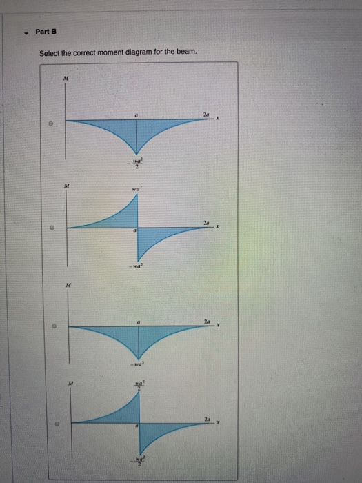
(Figure 1) wa 2a -wa 2wa 2wa x. 2a -2wa wa -Part B Select the correct moment diagram for the beam. 2a 2a 2a 24 Question : Part A Select the correct shear diagram for the beam. This problem has been solved! WITH SHEAR AND MOMENT DIAGRAMS American Forest & Paper Association w R V V 2 2 Shear M max Moment x DESIGN AID No. 6. AMERICAN WOOD COUNCIL The American Wood Council (AWC) is part of the wood products group of the ... Shear M 1 M max 3 8 x Figure 15 Beam Fixed at One End, Supported at Other-Uniformly Distributed Load beam from the left hand end and summing up the areas of shear force diagrams using proper sign convention. xThe process of obtaining the moment diagram from the shear force diagram by summation is exactly the same as that for drawing shear force diagram from load diagram.
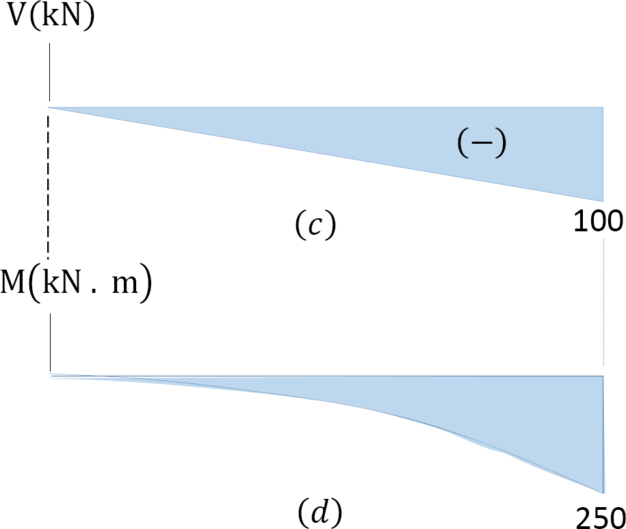
Select the correct shear diagram for the beam. (figure 1). • A beam is a structural member that is subjected primarily to transverse loads and negligible axial loads. • The transverse loads cause internal shear forces and bending moments in the beams as shown in Figure 1 below. w P V(x) M(x) x w P V(x) M(x) x Figure 1. Internal shear force and bending moment diagrams for transversely loaded beams. Select the correct shear diagram for the beam figure 1. This is the end of the preview. Draw the moment diagram for 10 points bonus for the beam shown in the figure below draw the shear diagram. Show all your work bonus points. In the figure below block 1 of mass m 1 slides from rest along a frictionl. The intensity of which varies from zero at ... If at a section distant from one of the ends of the beam, M represents the bending moment. V the shear force and w the intensity of loading, then. 1. dM/dx = V. 2. dV/dx = w. 3. dw/dx = y. (the deflection of the beam at the section) Select the correct answer using the codes given below: Problem 411 Cantilever beam carrying a distributed load with intensity varying from wo at the free end to zero at the wall, as shown in Fig. P-411. [collapse collapsed title="Click here to read or hide the general instruction"]Write shear and moment equations for the beams in the following problems. In each problem, let x be the distance measured from left end of the beam.
the axis of the beam consists of a shear force, V, and a bending moment, M. In determining beam responses, it is very convenient, if not essential, to first determine the shear and bending moment diagrams. The basic procedure for determining the shear and moment diagrams is to determine the values of V and M at various locations along the beam ... Correct problem 753 part a draw the shear diagram for the beam. Figure 1 draw the moment diagram for the beam. If there is an upward force ie a support then the sfd will start at this force above the x axis. Draw the moment diagram for the beam. Draw the moment diagram for the beam. Figure 1 click on add vertical line off to add discontinuity ... Q 6 For the shear force diagram shown in given figure The loaded beam will be Q 7 Match List-I (Type and position of force on cantilever) with List-II (Shape of moment diagram for cantilever) and select the correct answer using the codes given below the lists: Find step-by-step Engineering solutions and your answer to the following textbook question: Draw the shear and moment diagrams for the cantilever beam with the linear loading. Find the maximum magnitude of the bending moment M..
governs the complexity of its design. Shear force and bending moment diagrams quantify structural action of beams and cantilevers and are required for their rational design. Beams and cantilevers shown in Fig. 2.1 are known as fl exural elements. Fig. 2.1 Conventional simple beam supported at both ends. The beam supported at one end Transcribed Image Textfrom this Question. Part A Select the correct shear diagram for the beam (Figure 1) V WL * 5L 8 L WL 4 V WL 뿡 X ЗwL. 8 V WL 8 3L 8 WI V wL 8 3L 8 X Figure 3wL 8 Submit Request Answer Part B Select the correct moment diagram for the team. Select the correct shear diagram for the beam figure 1. Solution 43 1 simple beam. This preview has intentionally blurred sections. Shear and bending moment. Shear and bending moment diagrams for beam ab and determine the maximum. As shown in the figure below a uniform beam is supported by a cable at one. Shear and Moment Diagrams.The shear and moment diagrams shown in Fig. 6-6c are obtained by plotting Eqs. 1 and 2.The point of zero shearcan be found from Eq. 1: From the moment diagram, this value of x happens to represent the point on the beam where the maximum momentoccurs, since by Eq. 6-2, the slope From Eq. 2, we have = wL2 8 M max = w ...
Shear Force Diagram An Overview Sciencedirect Topics
Select the correct free-body diagram of segment AB of the beam in case (f) required to determine the internal loadings at B. Concentrated moment only The shear and moment diagrams for a beam have been obtained as shown.

Draw The Shear And Moment Diagram Part A Draw The Shear Diagram For The Beam Follow Homeworklib
Answer to: Select the correct shear diagram for the beam. (Figure 1) By signing up, you'll get thousands of step-by-step solutions to your homework...

Theoretical Spectroscopic Study Of Acetyl Open Research Europe
Free online beam calculator for generating the reactions, calculating the deflection of a steel or wood beam, drawing the shear and moment diagrams for the beam. This is the free version of our full SkyCiv Beam Software. This can be accessed under any of our Paid Accounts, which also includes a full structural analysis software.
Can You Draw The Shear Force And Bending Moment Diagrams Of The Beam Shown In The Figure Below Considering The Given Load Quora
Figure 4.1 Statically determinate beams A cantilever beam is built into a rigid support at one end, with the other end being free, as shown in Fig.4.1(b). The built-in support prevents displacements as well as rotations of the end of the beam.
Mechanics Of Solids Physics Britannica
Following are the important MCQ on shear force and bending moment diagram. 1) Shear force at any point on the beam is_______. a) algebraic summation of all forces on the beam. b) algebraic summation of all forces those are on the left or right side of the section. c) algebraic summation of all vertical upward forces acting on the beam.

Part A Draw The Shear Diagram For The Beam Follow The Sign Convention Figure 1 Part B Draw The Moment Diagram For The Beam Follow The Sign Convention Study Com
Problem 4.3-1 Calculate the shear force V and bending moment M at a cross section just to the left of the 1600-lb load acting on the simple beam AB shown in the figure. Solution 4.3-1 Simple beam 4 Shear Forces and Bending Moments 259 AB 800 lb 1600 lb 120 in. 30 in. 60 in. 30 in. M A 0: R B 1400lb M B 0: R A 1000lb Free-body diagram of segment ...
2
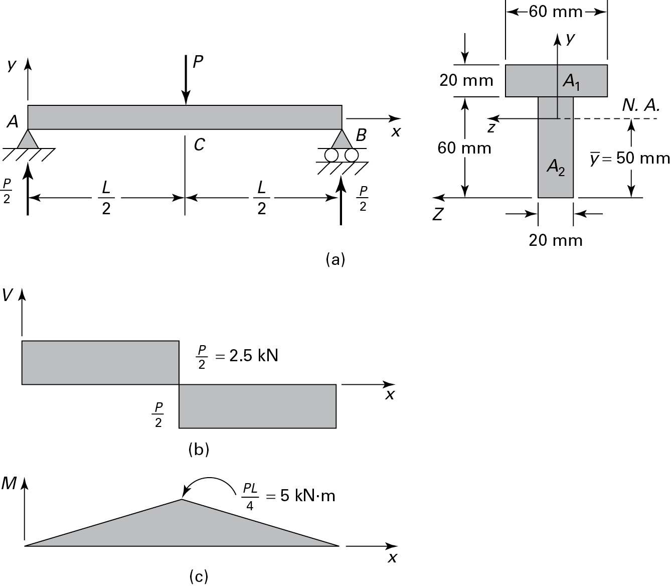
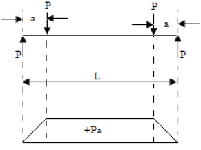
a) Calculate the shear force and bending moment for the beam subjected to a concentrated load as shown in the figure. Then, draw the shear force diagram (SFD) and bending moment diagram (BMD). b) If P = 20 kN and L = 6 m, draw the SFD and BMD for the beam. P kN L/2 L/2 A B EXAMPLE 4

The Shear Resistance Of A Member Without Shear Reinforcement According To Eurocode 2 The Error Of The Calculated Value And The Mechanical Explanation Of The Problem In International Review Of Applied Sciences
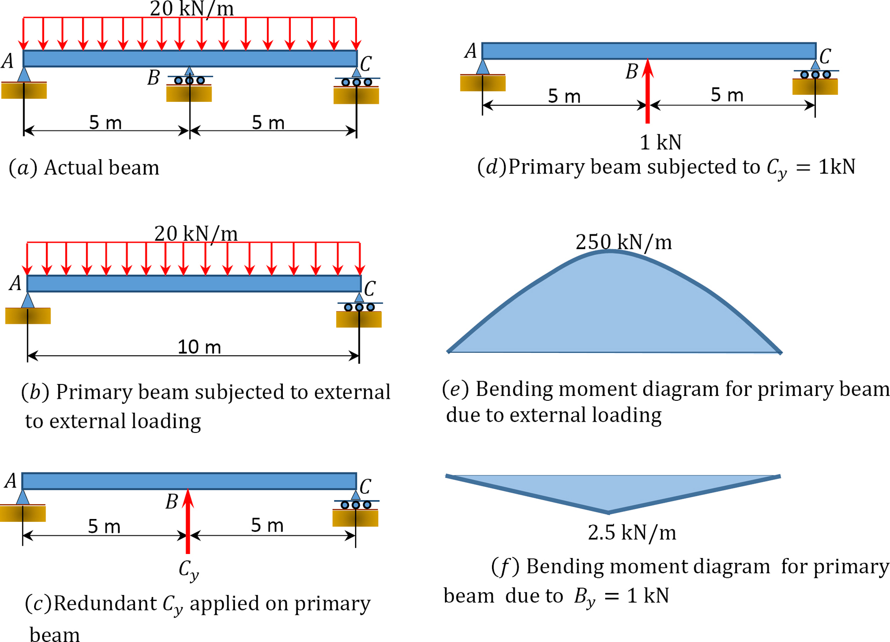
Shear and Moment Diagrams. Shear and Moment Diagrams. Consider a simple beam shown of length L that carries a uniform load of w (N/m) throughout its length and is held in equilibrium by reactions R 1 and R 2. Assume that the beam is cut at point C a distance of x from he left support and the portion of the beam to the right of C be removed.
1 4 Internal Forces In Beams And Frames Engineering Libretexts
Drawing Forces in the Beam: 12. Draw a diagram of the shear force in the beam. The shear in the end of the beam starts out at 0 lbs. However, since there is a reaction of 22,500 lbs on the left side of the beam, it will create that much shear in that location. The line load will cause this shear to decrease along the length
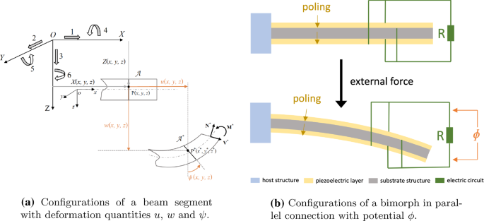
A Geometrically Nonlinear Shear Deformable Beam Model For Piezoelectric Energy Harvesters Springerlink
a) Select the correct shear diagram for the shaft in terms of the parameters shown. Figure b) Select the correct moment diagram for the shaft in terms of the parameters shown.
Solved Choose The Correct Shear Diagram For The Beam Follow Chegg Com
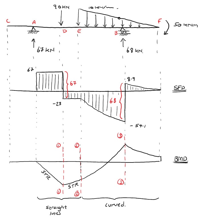
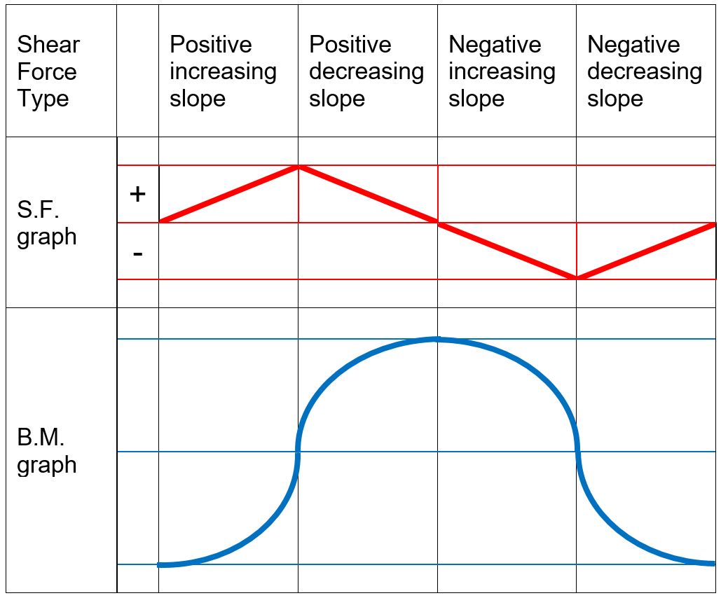
Beams -SFD and BMD V = V 0 + (negative of area under the loading curve from x 0 to x) M = M 0 + (area under the shear diagram from x 0 to x) If there is no externally applied moment M 0 at x 0 = 0, total moment at any section equals the area under the shear diagram up to that section When V passes through zero and is a continuous

Shear Force Diagram An Overview Sciencedirect Topics
beam from the left hand end and summing up the areas of shear force diagrams using proper sign convention. xThe process of obtaining the moment diagram from the shear force diagram by summation is exactly the same as that for drawing shear force diagram from load diagram.
Solved Part A Select The Correct Shear Diagram For The Chegg Com
WITH SHEAR AND MOMENT DIAGRAMS American Forest & Paper Association w R V V 2 2 Shear M max Moment x DESIGN AID No. 6. AMERICAN WOOD COUNCIL The American Wood Council (AWC) is part of the wood products group of the ... Shear M 1 M max 3 8 x Figure 15 Beam Fixed at One End, Supported at Other-Uniformly Distributed Load
2
(Figure 1) wa 2a -wa 2wa 2wa x. 2a -2wa wa -Part B Select the correct moment diagram for the beam. 2a 2a 2a 24 Question : Part A Select the correct shear diagram for the beam. This problem has been solved!

Early Breast Cancer Esmo Clinical Practice Guidelines For Diagnosis Treatment And Follow Up Annals Of Oncology

Draw The Shear And Moment Diagram Part A Draw The Shear Diagram For The Beam Follow Homeworklib
5 7 Normal And Shear Stresses Bending Of Beams Informit
1 10 Force Method Of Analysis Of Indeterminate Structures Engineering Libretexts
The Ultimate Guide To Shear And Moment Diagrams Degreetutors Com
Can You Draw The Shear Force And Bending Moment Diagrams Of The Beam Shown In The Figure Below Considering The Given Load Quora
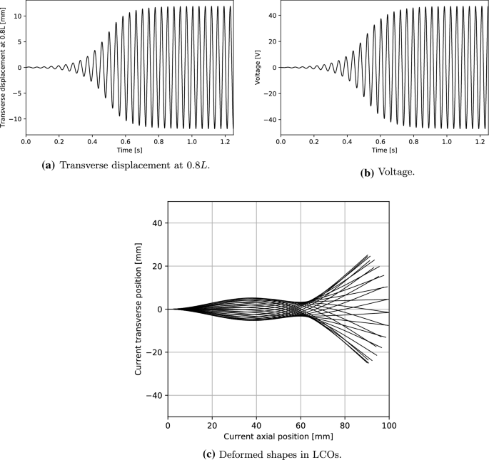
A Geometrically Nonlinear Shear Deformable Beam Model For Piezoelectric Energy Harvesters Springerlink
2
Beam Reactions And Diagrams Strength Of Materials Supplement For Power Engineering
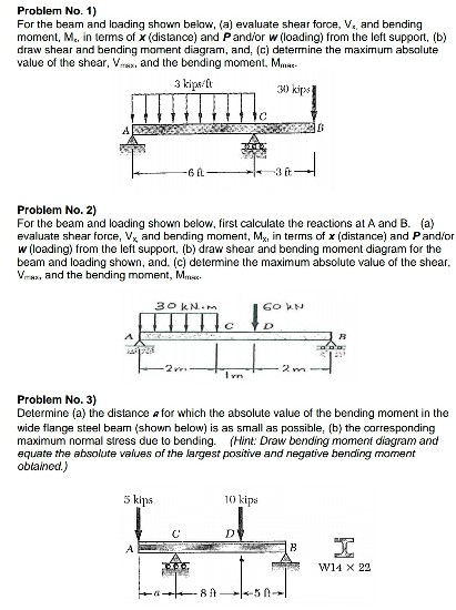
Solved For The Beam And Loading Shown Below A Evaluate Shear Force 1 Answer Transtutors
Test Bending Moment Shear Force Diagram 2 30 Questions Mcq Test
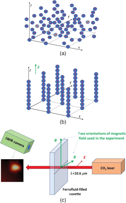
Experimental Observation Of Effective Gravity And Two Time Physics In Ferrofluid Based Hyperbolic Metamaterials
2

Achromatic Terahertz Airy Beam Generation With Dielectric Metasurfaces
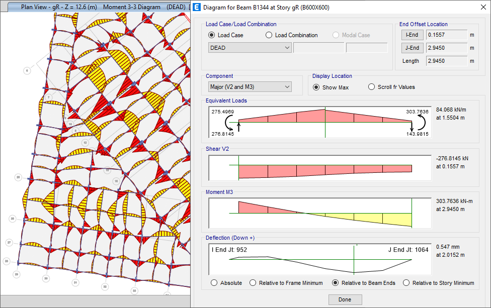
Etabs Features Building Analysis And Design
Room Temperature Thz Qcl Source Optical Materials Hamamatsu Photonics

Practice Exams Mcgraw Hill Education Access Engineering
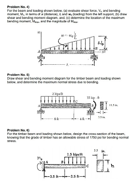
Solved For The Beam And Loading Shown Below A Evaluate Shear Force 1 Answer Transtutors

Drawing Shear And Moment Diagrams For Beam Youtube

Keywords Keywords Glossary Of Tem Terms Jeol
2

Theorems For Flexural Design Of Rc Members Journal Of Structural Engineering Vol 142 No 5
Trust Is Good Control Is Better A Review On Monitoring And Characterization Techniques For Flow Battery Electrolytes Materials Horizons Rsc Publishing Doi 10 1039 D0mh01632b
Free Body Diagram Wikipedia
2
0 Response to "39 select the correct shear diagram for the beam. (figure 1)"
Post a Comment