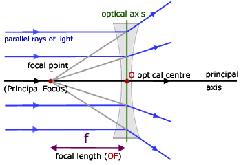
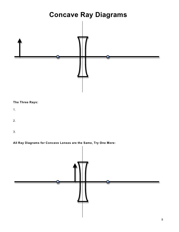
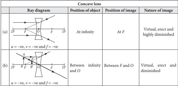
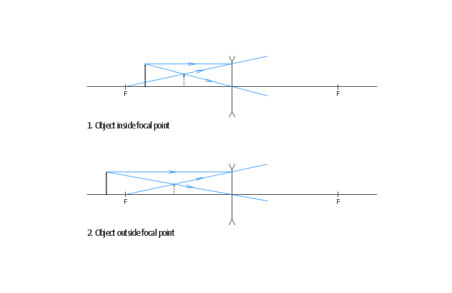
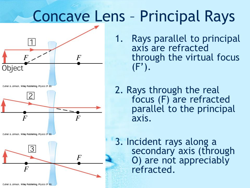
41 ray diagram for concave lenses
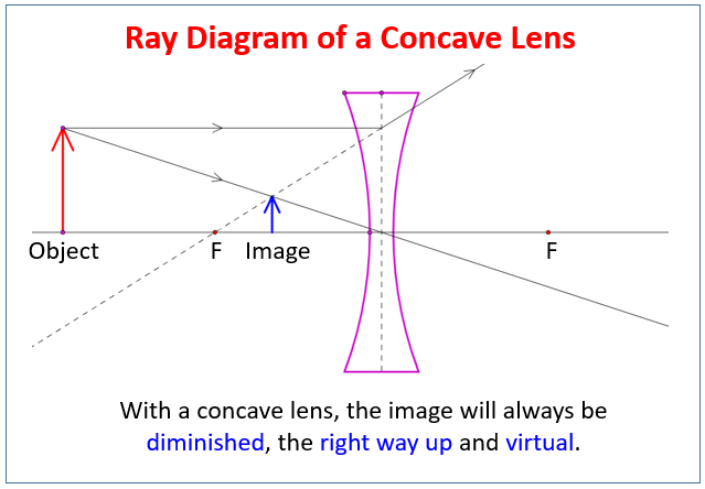
The ray diagram above illustrates that the image of an object in front of a double concave lens will be located at a position behind the double concave lens. Ray Diagrams for Concave Lenses. The ray diagrams for concave lenses inside and outside the focal point give similar results: an erect virtual image smaller than the object. The image is always formed inside the focal length of the lens.
We kinda skipped over the optics and wave section in my AP Physics 2 class. I'm doing some last minute studying and I'm wondering what I need to know for optics and waves? Like I know ray diagrams for concave and convex lenses and mirrors, as well as snells law but do I also have to know phase changes, thin film, double slit, etc? And if I do need to know those things what are some good resources to learn them in the next few days? Thanks for any help!

Ray diagram for concave lenses
Nearsightedness — the condition where a person can see near objects clearly but distant objects are blurry — typically is easily corrected with prescription eyeglasses or contact lenses. Lenses used to correct nearsightedness are concave in shape. In other words, they are thinnest at … Guidelines for rays falling on the concave and convex lenses · When a ray strikes concave or convex lenses obliquely at its pole, it continues to follow its path ... This is because it is easier to get higher magnification with two lenses rather than just one. Use of one lens can magnify 5 times more and using a second will magnify 7 times, and you will get an overall magnification of 35 which is not possible in one lens. It’s an easy procedure than to get magnification by a factor of 35 with a single lens. A ray diagram of the microscope arrangement is ...
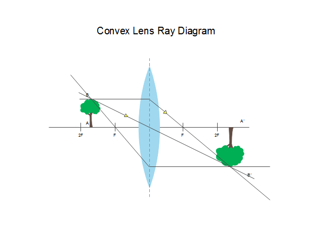
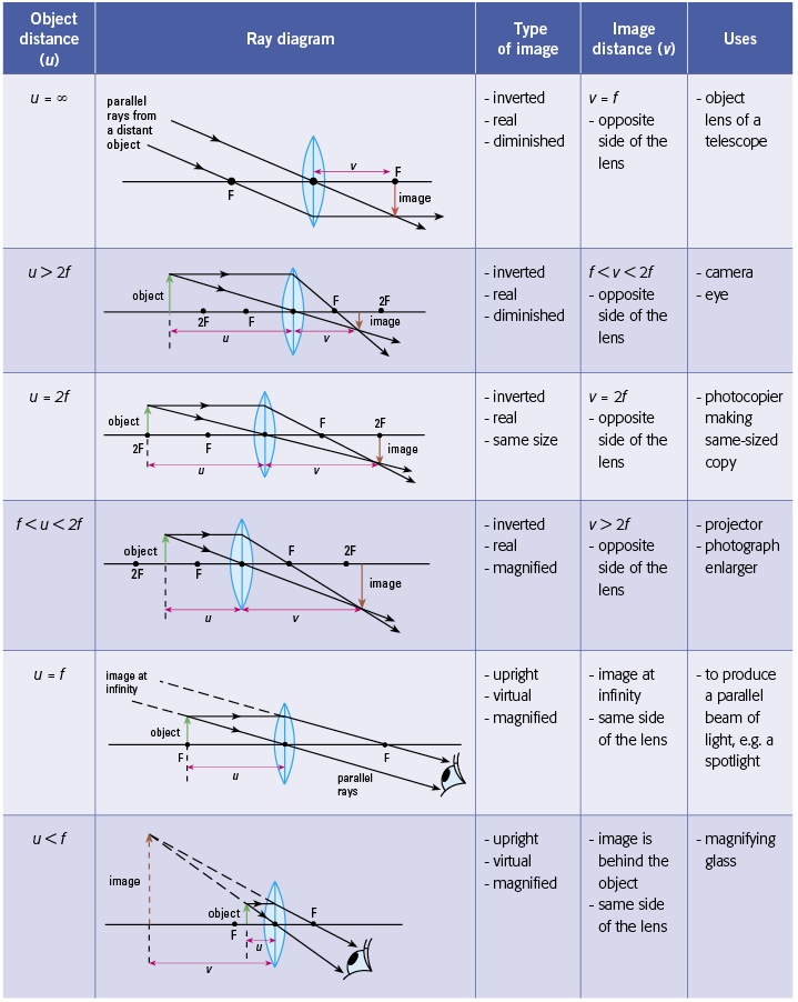
Ray diagram for concave lenses. Hey guys, so after hours of study/confusion (idk maybe I'm just like...physics challenged and had trouble...that happens often to me with topics)...I've boiled it down to the following. Hopefully, it can help you all solve these kinds of problems; NS Content review goes over how to draw the diagrams, etc., but I really doubt any of us will be drawing diagrams on test day. Things to be aware of that don't have to do with the 5 steps: --> Snell's Law and refraction/reflection (i.e. what ... Apr 11, 2020 · Image formation by convex lens ray diagrams. Image formation in a convex lens can be explained with the help of three principal rays shown in the figure. The ray parallel to the principal axis passes through the focal point after refraction by the lens. The ray passing through optical centre passes straight through the lens and remains undeviated. The ray passing through the focal point becomes parallel to the principal axis after refraction by the lens. refraction by spherical lenses, we must first adopt a sign convention for measuring distances. ... reflection of an incident ray on (a) concave spherical mirror, and (b) convex spherical mirror. ± Ray Optics and Optical Instruments 313 virtual if the rays do not actually meet but appear to diverge from the point when produced backwards. An image is thus a point-to-point correspondence with ... Method for drawing ray diagrams – Concave lens. A concave lens ray diagram is a simple way of visualising the path that light rays take when passing through a concave lens. To draw a ray diagram you only need to draw two ray lines. This is sometimes referred to as “the two rules of refraction for diverging lenses”.
Ray tracing diagram for concave lens. The vector stencils library "Optics" contains 17 symbol icons: reflecting surface; convex and concave lens with and without optic axis, body or ray; ray; parallel beam of light; point light source; prism with and without ray path; refraction. Use these shapes for drawing physical schemes of geometrical optics experiments and ray tracing diagrams in the ConceptDraw PRO diagramming and vector drawing software extended with the Physics solution from the ... The theme of this unit has been that we see an object because light from the object travels to our eyes as we sight along a line at the object. Similarly, we see an image of an object because light from the object reflects off a mirror and travel to our eyes as we sight at the image location of the object. From these two basic premises, we have defined the image location as the location in space where light appears to diverge from. Ray diagrams have been a valuable tool for determining the path taken by light from the object to the mirror to our eyes. In this section of Lesson 3, we will investigate the method for drawing ray diagrams for objects placed at various locations in front of a concave mirror. Apr 26, 2020 · For a Concave lens,There are only 2 casesThey areObject is Placed at InfinityObject is Placed between Infinity and Optical CenterCase 1 - Object is Placed at infinityIn this Case, Object is kept far away from mirror (almost at infinite distance)So, we draw rays parallel to principal axisSince ray pa TL;DR *I am farsighted and recently had an eye exam. Optometrist said I needed a progressive lens. I asked a plethora of questions but didn't get an answer I was satisfied with. I'm worried I got taken advantage of, but before I shell out MORE money for a second opinion I wanted to run it by you folks* Now, I am a curious chap and I ask a lot of questions. I pestered the optometrist with questions until he was annoyed - but still didn't get an explanation that satisfied me. As best I coul...
Stability diagram for a two-mirror cavity. Blue-shaded areas correspond to stable configurations. Only certain ranges of values for R 1, R 2, and L produce stable resonators in which periodic refocussing of the intracavity beam is produced. If the cavity is unstable, the beam size will grow without limit, eventually growing larger than the size of the cavity mirrors and being lost. By using ... 06.11.2020 · (i) Based on the diagram shown, what kind of lenses would Sumati need to make the telescope? a) Concave lenses . b) Convex lenses . c) Bifocal lenses . d) Flat lenses (ii) If the powers of the lenses L 1 and L 2 are in the ratio of 4:1, what would be the ratio of the focal length of L 1 and L 2? a) 4:1 . b) 1:4 . c) 2:1 . d) 1:1 Draw a ray diagram to show how an image is formed by a concave lens. Describe the properties of an image produced by a concave lens. Draw different ray diagrams with the object at different places in relation to the focus and find out where the image appears. In a ray diagram, a convex lens is drawn as a vertical line with outward facing arrows to indicate the shape of the lens. The distance from the lens to the ...
Section 3: Concave Lenses 12 3. Concave Lenses Concave lenses always produce upright, virtual images. For aconcave lens, the lens equation is the same but the value of fis nownegative. Ray diagrams for such lenses are drawn using: a ray from the top of the object through the middle of the lens; a ray from the top of the object parallel to the ...
This is because it is easier to get higher magnification with two lenses rather than just one. Use of one lens can magnify 5 times more and using a second will magnify 7 times, and you will get an overall magnification of 35 which is not possible in one lens. It’s an easy procedure than to get magnification by a factor of 35 with a single lens. A ray diagram of the microscope arrangement is ...

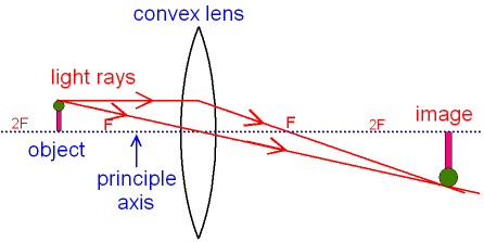
The Photons Of Light Then Travels In All Directions Simple Convex Lens Ray Diagram Transparent Png 600x355 Free Download On Nicepng
Guidelines for rays falling on the concave and convex lenses · When a ray strikes concave or convex lenses obliquely at its pole, it continues to follow its path ...

Convex Lens Concave Lens How To Determine Focal Length Ray Diagrams Image Properties Real Virtual Inverted Size Correction Of Eye Defects Causes Of Long Sight Short Sight Igcse Gcse 9 1 Physics Revision Notes
Nearsightedness — the condition where a person can see near objects clearly but distant objects are blurry — typically is easily corrected with prescription eyeglasses or contact lenses. Lenses used to correct nearsightedness are concave in shape. In other words, they are thinnest at …
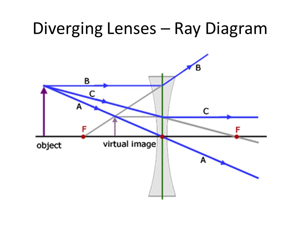
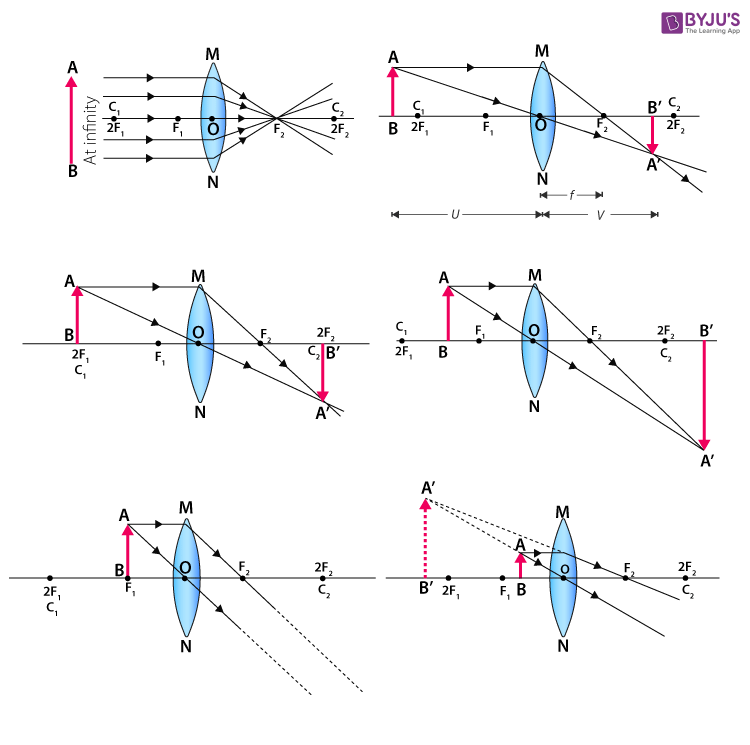
Images Formed By Lenses Ray Diagrams For Lenses Ray Diagrams Can Be Used To Predict Characteristics Of Images Using 3 Rays Just Like For Concave Ppt Download
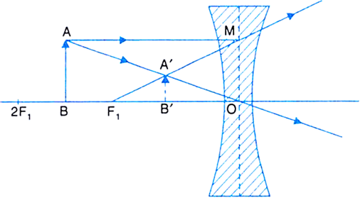
Draw A Ray Diagram To Show The Formation Of The Image Of An Object Placed Between F And 2f Of A Thin Concave Lens Deduce The Relation Between The Object Distance The
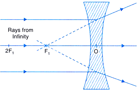
With The Help Of Ray Diagrams Explain The Formation Of Images By A Concave Lens For The Following Positions Of The Object I Object At Infinity Ii Object Between Infinity And Optical Centre O












0 Response to "41 ray diagram for concave lenses"
Post a Comment