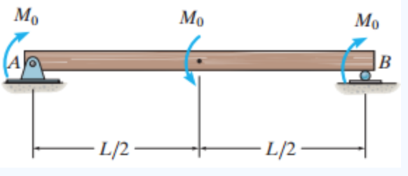
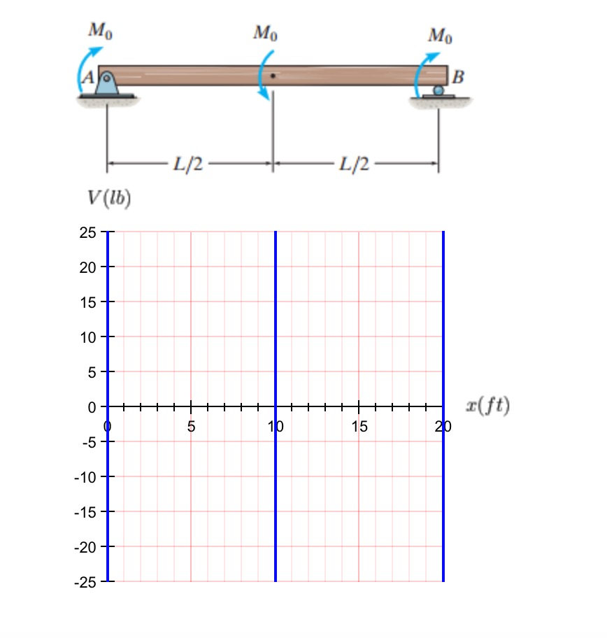
39 draw the shear diagram for the beam. assume that m0=200lb⋅ft, and l=20ft.
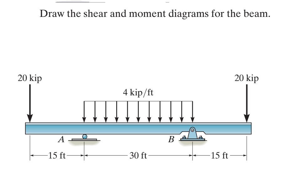
Draw the shear and moment diagrams for the beam and determine the shear and moment in the beam as functions of x, where 4 ft < x < 10 ft. 200 lb ft B x 4 ft 4 ft 150 lb/ft 6 ft 200 lb ft A Ans. a M =-75x2 + 1050x - 3200 Ans.-200 - 150(x - 4) (x - 4) 2 +©M = 0; - M + 450(x - 4) = 0 V = 1050 - 150x + c©F y = 0;-150(x - 4) - V + 450 = 0 M (lb ft ...
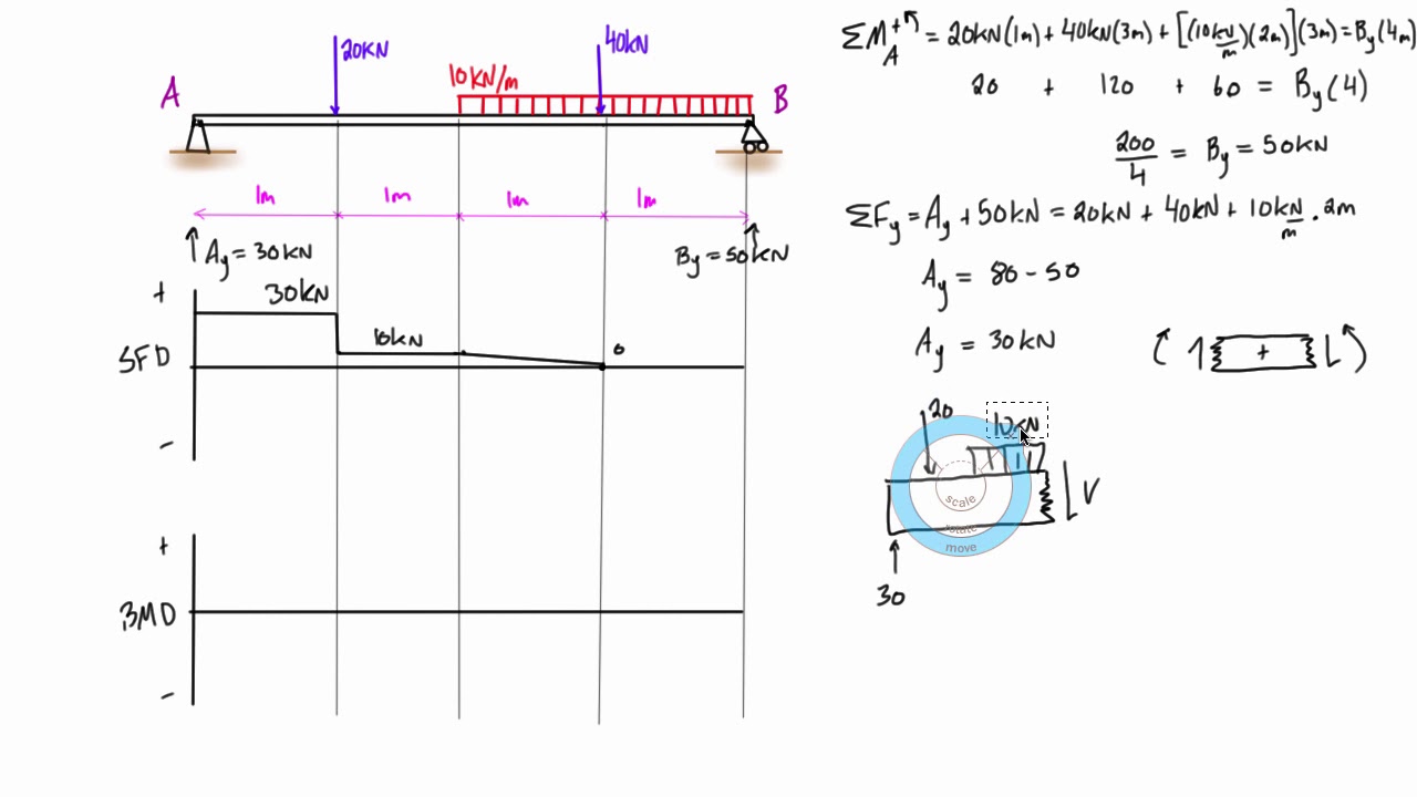
The net force acting on the beam is zero but there is a couple acting on the system. 3 2-D Moment and Couple α F A r d M A For 2-D (in-plane rotation) problem, moment vector always points perpendicular to the plane. 5 ft 4 ft A B 900 lb 200 lb A y A x B y 4. The force F = {400i - 100j - 700k} lb acts.
Publishing platform for digital magazines, interactive publications and online catalogs. Convert documents to beautiful publications and share them worldwide. Title: Dynamics 11th edition, Author: cireneulucio, Length: 844 pages, Published: 2010-07-07

Draw the shear diagram for the beam. assume that m0=200lb⋅ft, and l=20ft.
4.3 Shear- Moment Equations and Shear-Moment Diagrams The determination of the internal force system acting at a given section of a beam : draw a free-body diagram that expose these forces and then compute the forces using equilibrium equations. The goal of the beam analysis -determine the shear force V and
draw the shear diagram for the beam. assume that m0=200 lb⋅ft and l=20ft › ... draw the shear diagram for the beam. set m0 = 500 n⋅m l = 8 m › draw the shear diagram for the beam. set p = 600 lb a = 5 ft b = 7 ft › draw the shear diagram for the beam. set p = 800 lb a = 5 ft l = 12 ft. Draw The Shear Diagram For The Beam ...
The engine crane is used to support the engine, which has a weight of 1200 lb. Draw the shear and moment diagrams of the boom ABC when it is in the horizontal position shown. 3 ft 5 ft. A B C. 4 ft 1200 lb. 1200. ΣM B = 0 5 R A = 2000lb(5 ft ) ΣFY = 0-2000 RB = 2000lb + 1200lb RB = 3200lb V A = −2000lb V AL = −2000lb-6000 VB = −2000lb ...
Draw the shear diagram for the beam. assume that m0=200lb⋅ft, and l=20ft..
acceleration (ft/sec2, m/sec2); width of the base of a retaining wall for pressure calculation (ft, m); equivalent square column size in spread footing design (in, ft, mm, m); distance used in beam formulas (ft, m); depth of the effective compression block in a concrete beam (in, mm) a area bounded by the centerline of a thin walled section ...
Problem 4.3-3 Determine the shear force V and bending moment M at the midpoint of the beam with overhangs (see figure). Note that one load acts downward and the other upward. Solution 4.3-3 Beam with overhangs 260 CHAPTER 4 Shear Forces and Bending Moments P P b L b P ¢1 2b L ≤ (upward) R A 1 L [P(L b b)] ©M B 0 Free-body diagram(C is the ...
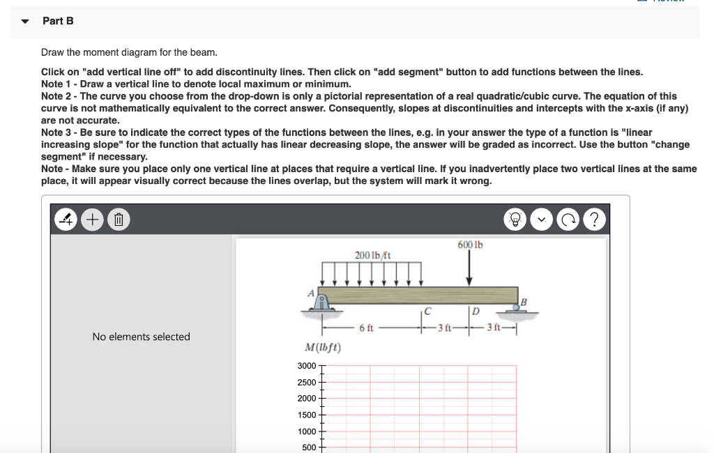
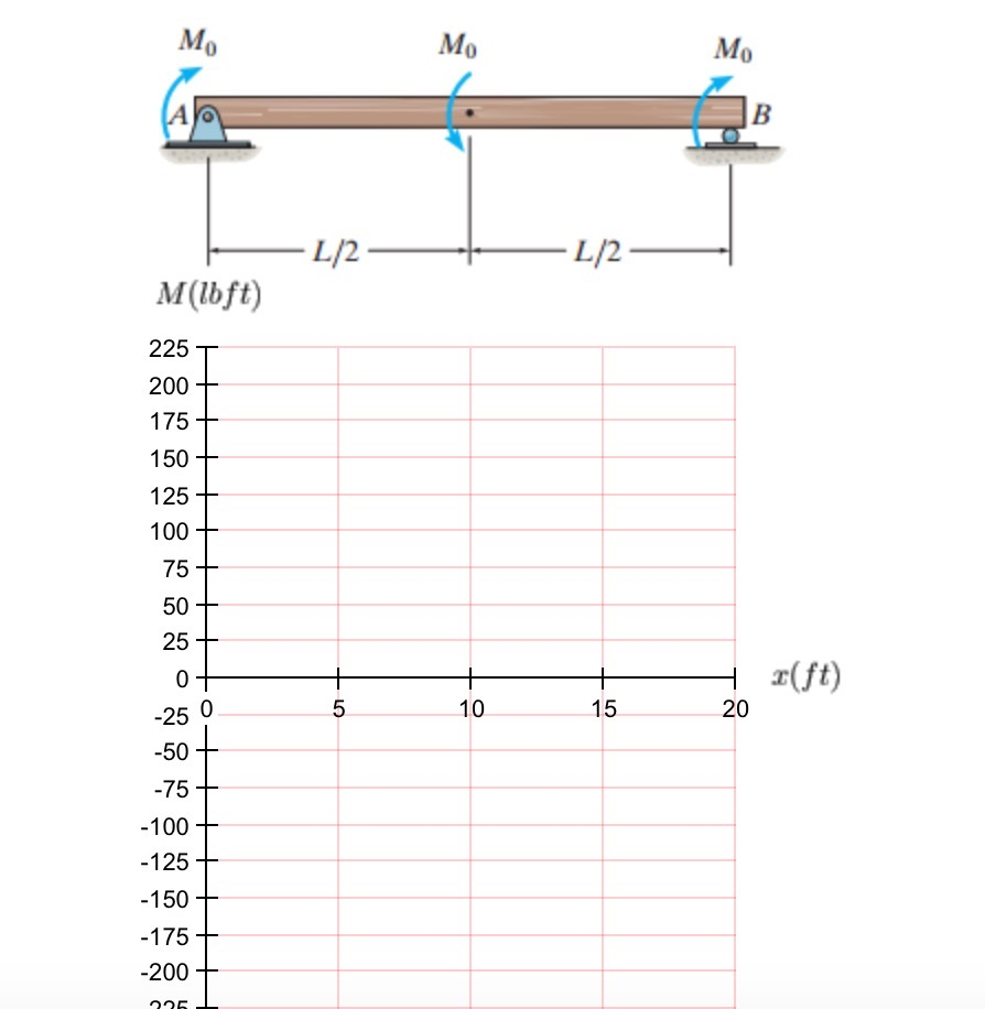
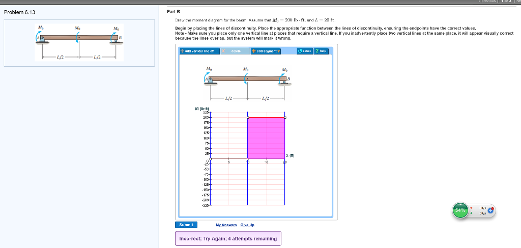
Draw the shear diagram for the beam. Assume that M0=200lb⋅ft, and L=20ft. Begin by placing the lines of discontinuity. Place the appropriate function between the lines of discontinuity, ensuring the endpoints have the correct values. Note - Make sure you place only one vertical line at places that require a vertical line. If you.
speed of 75 ft>s just before it hits the barrier. F = (90(103)x1>2) x SOLUTION Principle of Work and Energy: The speed of the car just before it crashes into the barrier is .The maximum penetration occurs when the car is brought to a stop, i.e., . Referring to the free-body diagram of the car,Fig. a, W and N do no work;however, does negative ...
No part of this Manual may be displayed, reproduced or distributed in any form or by any means, without the prior written permission of the publisher, or used beyond the limited distribution to
freetablewooden By special reader request, the very fabulous Morris Chair! To construct your own cushions using foam, the measurements would be 20″ x 24″ ...
base cabinet height bathroom 👽King'S Fine Woodworking Inc. We believe in; Looking after our people, small empowered teams, complete transparency, test, learn repeat, community
Fishbone Infographics Template s Free Google Slides theme and PowerPoint template. Fishbone diagram s, also known as Ishikawa diagram s, are powerful visual representations. More than often, they help to identify the possible causes of an issue. The problem is placed as the head of the fishbone, while the spines represent the roots of the obstacle. FishBone Diagram Template s for PowerPoint ...
Draw the shear diagram for the beam. Assume that M0=200lb⋅ft, and L=20ft. Begin by placing the lines of discontinuity. Place the appropriate function between the lines of discontinuity, ensuring the endpoints have the correct values. Note - Make sure you place only one vertical line at places that require a vertical line. If you.
3 PROPRIETARY MATERIAL. © 2010 The McGraw-Hill Companies, Inc.All rights reserved. No part of this Manual may be displayed, reproduced or distributed in any form or ...
draw the shear diagram for the beam. assume that m0=200 lb⋅ft and l=20ft › draw the shear diagram for the beam. assume that w0=10kip/ft and l=18ft. Draw The Shear Diagram For The Beam Written By admin. Sunday, June 21, 2020 Edit. Draw The Shear Diagram For The Beam. Transcribed Image Text from this Question.
Moment of about point A M F r sin Fd A (α) = × ⋅== M rF A. Merim (2-27)] 2) A prybar is used to remove a nail as shown. Neglect the weight of the beam. (4) where is the position vector measured from the moment center to any point along the line of action of the force vector. B) The net force and net moment are equal to 0.
Engineering mechanics statics (7th edition) - j. l. meriam ...
PROBLEM 08 - 0268: Two long wooden planks form a T section of a beam as the twisting moment is 60,000 lb-ft and the shear force Determine the fiber stress at a point 2 in. 4 L = span length of the bending member, ft. SOLUTION Free-Body Diagram of Rod AB: — (650 — 250) 115.
329 6–1. draw the shear and moment diagrams for the shaft ...
Transcribed image text: Problem 6.13 Part A Draw the shear diagram for the beam. Assume that Mo 200 lb.ft, and L 20 ft. Begin by placing the lines of discontinuity. Place the appropriate function between the lines of discontinuity, ensuring the endpoints have the correct values Note Make sure you place only one vertical line at places that require a vertical line.
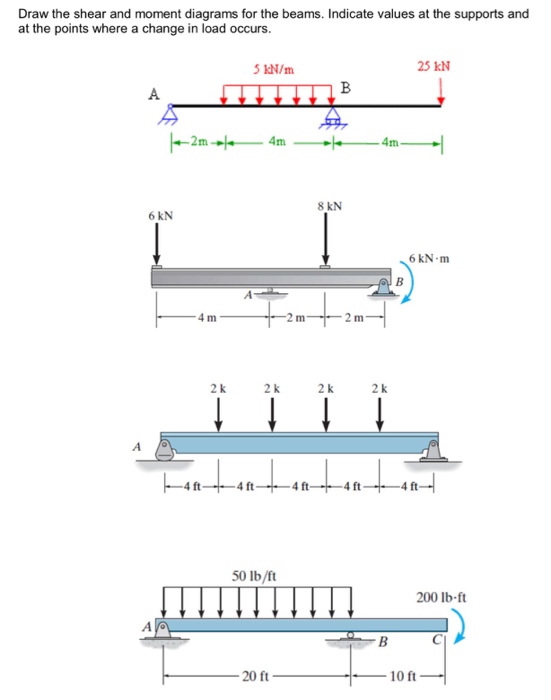
Solved draw the shear and moment diagrams for the beams ...
Select a page from the Stihl BR 400 Backpack Blower diagram to view the parts list and exploded view diagram.All parts that fit a BR 400 Backpack Blower.Pages in this diagram.A-Crankcase. B_-Rewind starter. B-Rewind starter. C_-Air filter. C-Air filter. D_-Carburetor HD 4A.
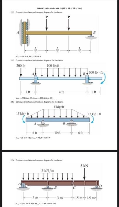
Solved megr 2100 - statics hw 22 (22.1, 22.2.22.3, 22.4 ...
Knowing that for each cable TA = 3100 N and TB = 3300 N, determine (a) the angular acceleration of the roll, (b) the acceleration of its mass center. SOLUTION Data: m = 1200 kg I = mk 2 = (1200) (0.150) 2 = 27 kg ⋅ m 2 1 1 r = d = (0.100) = 0.050 m 2 2 TA = 3100 N TB = 3300 N (a) Angular acceleration.
Solved
Draw the shear diagram for the beam. Assume that M0=200lb⋅ft, and L=20ft. Begin by placing the lines of discontinuity. Place the appropriate function between the lines of discontinuity, ensuring the endpoints have the correct values. Note - Make sure you place only one vertical line at places that require a vertical line.
Statics and dynamics 10th.ed johnston
Beam Calculator Online (Calculate the reactions, Draws Bending Moment, Shear Force, Axial Force) We updated the beam calculator interface and added additional features for calculating beams (calculation of statically indeterminate beams, image saving and section selection)! GO TO NEW INTERFACE (BEAM)>. GO TO NEW INTERFACE (FRAME/TRUSS)>.
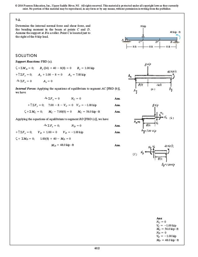
Solution
Determine the internal normal force, shear force, and moment acting at point C and at point D, which is located just to the right of the roller support at B. (a) Compute the moment of the force P about O by resolvingit into horizontal and vertical components. Let F = 200 lb, a = 3 ft, b = 4 ft, and c = 6 ft.

Statics 7.71 - draw the shear and moment diagram for the beam ...
College of Engineering - Purdue University

Drawing shear and moment diagrams for beam
Academia.edu is a platform for academics to share research papers.
329 6–1. draw the shear and moment diagrams for the shaft ...
draw free-body diagrams of bolt HJ and of the portion of the bolt located between the two planes (Fig. 1.19). Observing that the shear P in each of the sections is P = F∕2, the average shearing stress is τave = P F∕2 F = = A A 2A (1.10) H FC F K P K' L F L' P FD J (a) (b) Fig. 1.19 (a) Diagram of bolt in double shear;
Shear force and bending moment diagram example #5: mixed distributed and point loads
1. draw sfd and bmd for diagram 2.a simply supported beam of span 6 m carries two point loads of 30 kn each at 2 m and 4 m from left support. Draw the shear and bending moment diagram for the beam shown and find the value of the maximum bending stress. This case is a Simple Beam Concentrated Load at a Point.
Answered: draw the shear and moment diagrams for… | bartleby
Dyp gre mdm 7e(eng)
Solved draw the shear diagram for the beam. assume that ...
Chapter 7
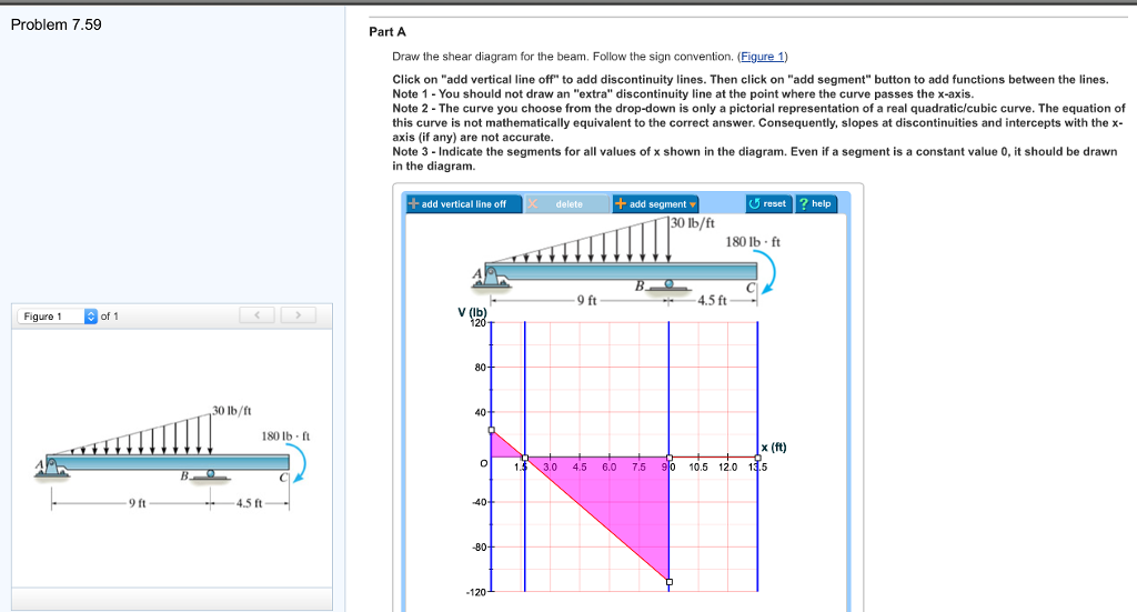
Solved problem 7.59 part a draw the shear diagram for the ...
Solved draw the shear diagram for the beam. assume that ...
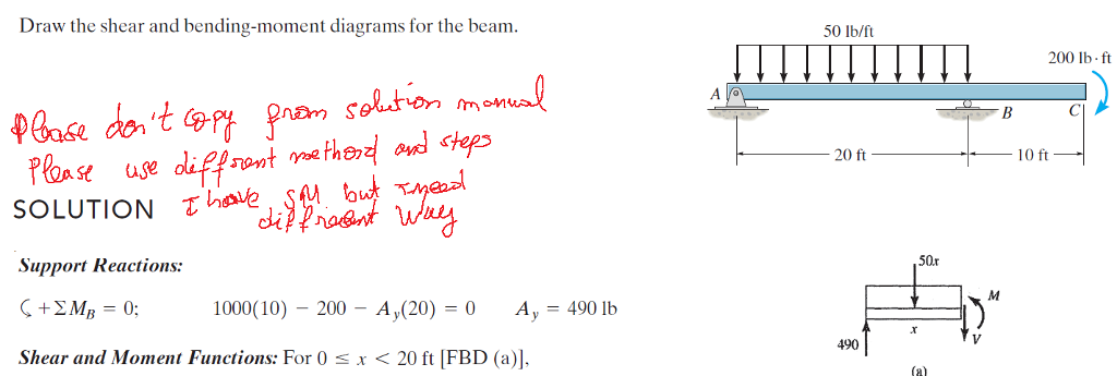
Solved draw the shear and bending-moment diagrams for the ...

Mechanics of materials pages 201 - 250 - flip pdf download ...

Mechanics of materials pages 201 - 250 - flip pdf download ...

Pdf) duiuyioupoipo | tachibana aki - academia.edu
Solved problem 6.13 part a draw the shear diagram for the ...

Find the distribution (asfunctions of xl of the noripal (n ...

Vector mechanics for engineers chapter 07.pdf - pdfcoffee.com
Solved draw the shear diagram for the beam. assume that ...

Drawing shear and moment diagrams for beam
329 6–1. draw the shear and moment diagrams for the shaft ...
Solution
Problem 7-1 the column is fixed to the floor and is subjected ...
Solved draw the shear diagram for the beam. draw the | chegg.com
329 6–1. draw the shear and moment diagrams for the shaft ...

Calaméo - dynamics 11th edition
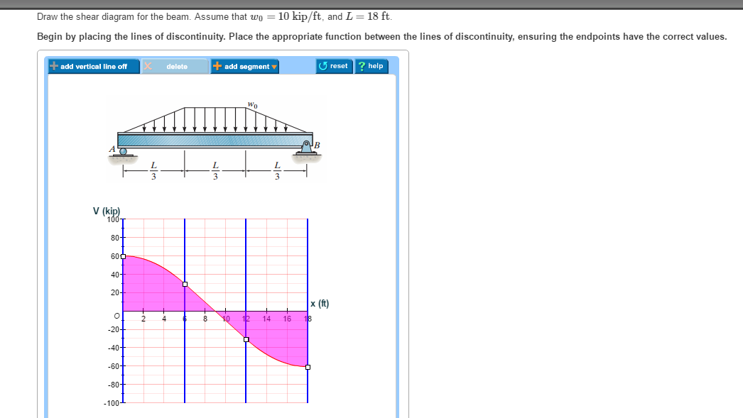
Solved draw the shear diagram for the beam. assume that wo ...
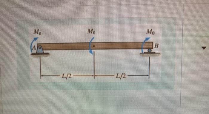
Solved mo mo m b l/2 l/2 draw the shear diagram for the ...
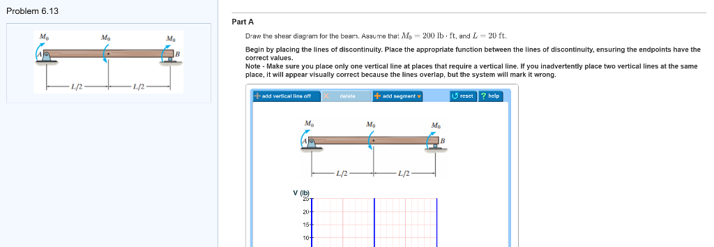
Solved problem 6.13 part a draw the shear diagram for the ...

Pdf) problem 2.1 | adian sixx - academia.edu
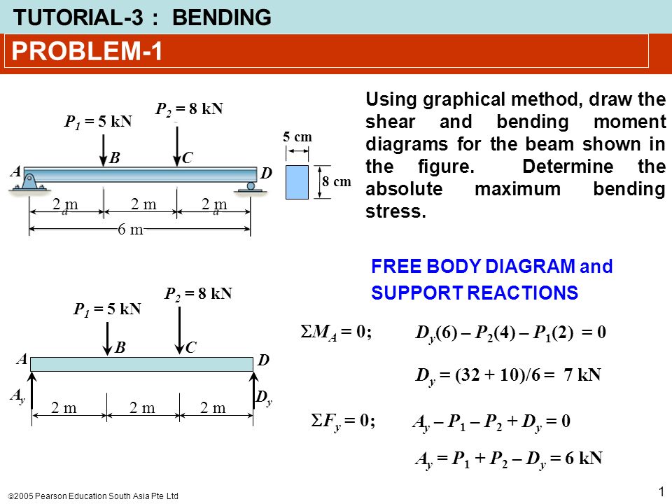
Problem-1 using graphical method, draw the shear and bending moment diagrams for the beam shown in the figure. determine the absolute maximum bending.

Pdf) problem 6.1 | moon scream - academia.edu
0 Response to "39 draw the shear diagram for the beam. assume that m0=200lb⋅ft, and l=20ft."
Post a Comment