40 determine the reaction at the roller support and draw the bending moment diagram
Manley H Beam Rods Evo Xl. December 2, 2021 - by Arfan - Leave a Comment. Con rod mitsubishi 4g93 pin 19mm h beam manley steel h beam connecting rods extreme psi your 1 source for in manley turbo tuff pro i beam manley performance sport …. Read More. Determine the reaction at the roller support and draw the bending moment diagram for the beam and loading shown. Step-by-step solution. Step 1 of 5. Draw ...
a) Free Body Diagram of Beam showing loading conditions. b) Loads and reaction acting on the beam. c) Shear Force Diagram d) Bending Moment Diagram. Download : Download high-res image (48KB) Download : Download full-size image; Fig 4. CAD model of single roll and shaft assembly.
Determine the reaction at the roller support and draw the bending moment diagram
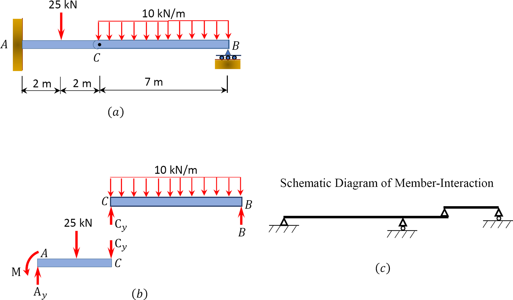
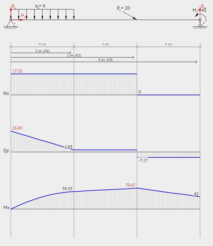
This online calculator shows internal forces diagram s for the simple (two-support) beam, pinned at one end and roller supported at the other, under a loading system. The calculator graphically depicts the bending moment M and the shear force Q acting along the bar. Plotting is necessary to determine the position of the most loaded (dangerous ... Welcome to the Multi-span Beam Calculator. Calculate the support reactions and draw the Bending Moment diagram, Shear Force Diagram, Axial Force Diagram. Determine the maximum bending moment. Please answer for me QUESTION TWO Determine the support reactions and draw the shear and bending moment diagrams for the two- span beam structure shown in Figure Q2 using the method of consistent deformations. 250 KN 25 k
Determine the reaction at the roller support and draw the bending moment diagram. In this video I walk you threw read ing the Moody diagram.The moody diagram is useful in obtaining the friction fac to r for a closed pipe system. SI based Moody Diagram.The Moody friction fac to r - λ (or f) - is used in the Darcy-Weisbach major loss equation. The coefficient can be estimated with the diagram below: If the flow is transient - 2300 < Re < 4000 - the flow varies between ... There is pin support at point A and a roller support at point B. The distance from A to B is 5 m. The distance from se ... determine the support reactions, sketch the shear force diagram and sketch the bending moment diagram indicating the maximum value(s). If can provide the calculation in detail . Determine the reaction at the roller support, and draw the bending moment diagram for the beam and loading shown. Step-by-step solution. Determine the reaction at the roller support and draw the bending moment diagram for the beam and loading shown. Step-by-step solution. Step 1 of 4. Draw ...
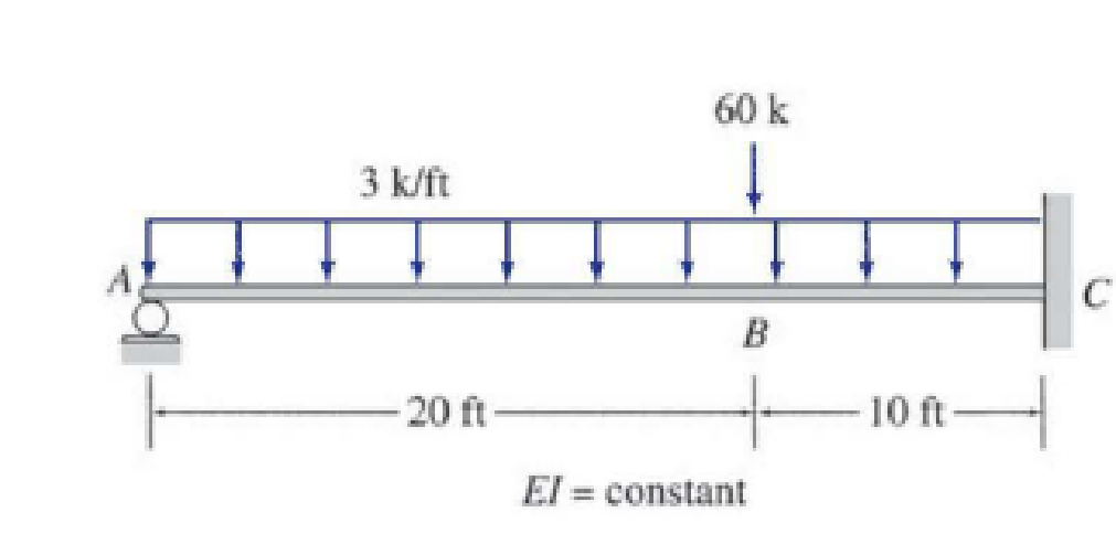
For the beam and loading shown, determine (a) the reaction at the roller support, (b) the deflection at point C. Nov 11, 2021 For the beam and loading shown, determine (a ) the reaction at point C, (b) the deflection at point B. Use E = 190 GPa. 12 kN/m W460 x 52 6 m 4 m They are composed of planar, bending- and shear-resistant shell elements and present an ideal situation for the constructional use of glass. The ridge-and-furrow principle developed by the English greenhouse pioneer J. C. Loudon and used to great success by J. Paxton with his Crystal Palace in 1851 is an early example of folded glass roof ... Determine the reaction at the roller support and draw the bending-moment diagram for the beam and loading shown. Step-by-step solution. Bending moment: It is the degree of bending produced on the beam when an arbitrary load acts on it. Usually moment is said to prevail on a beam or structure that is acted upon by a perpendicular force triggering rotation. Determine the reactions at support using the free body diagram of the entire beam and equilibrium conditions.
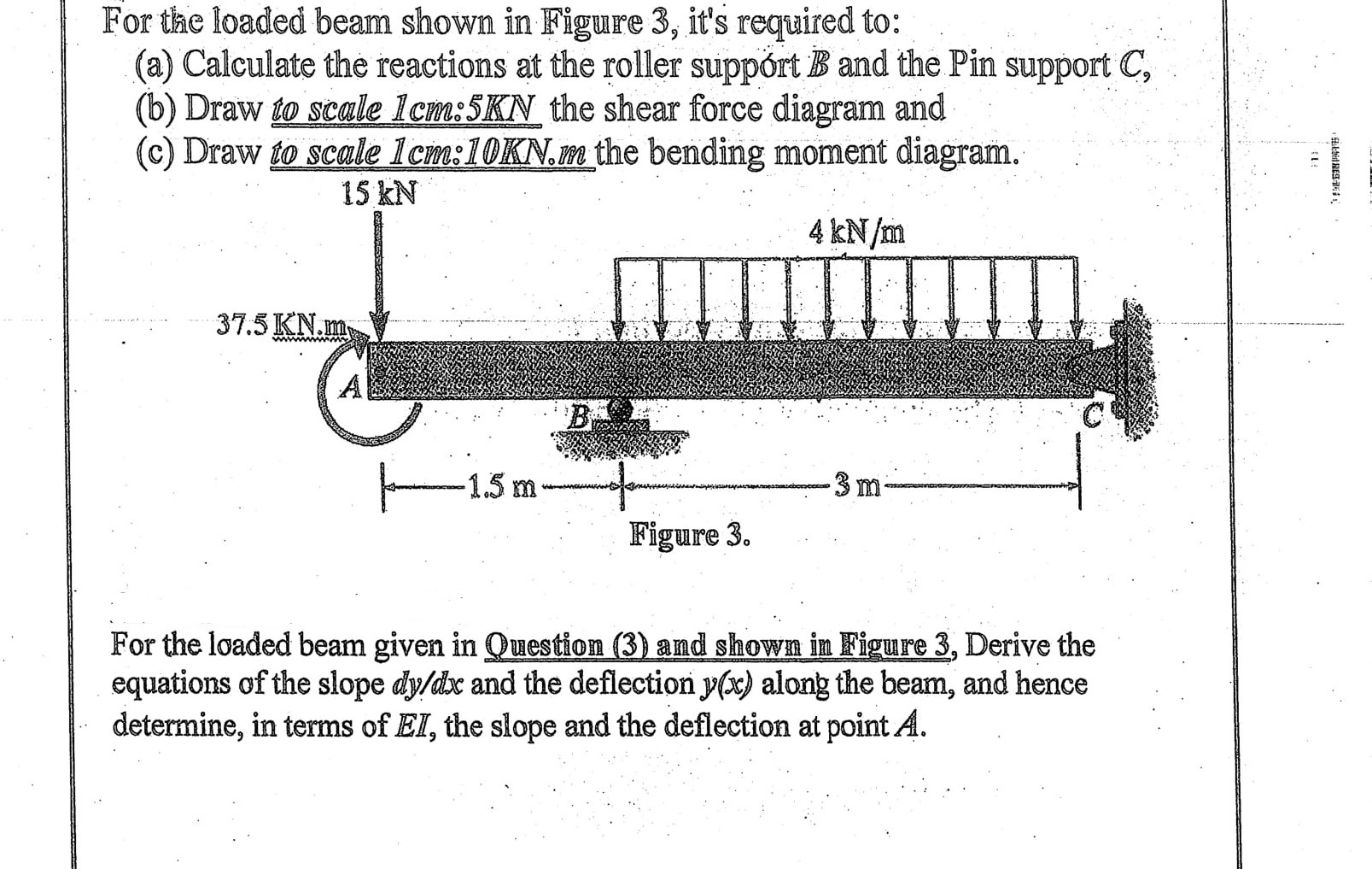
We first calculate for the reactions on the support in order to be able to draw the shear diagram. Draw the shear force and bending moment diagram for this loading. This tutorial goes over how to draw the shear force diagram, bending moment diagram, and deflected shape of a simply supported beam with a . Shear force and bending moment diagrams. Hey everyone, I need some help with a question I have, I think I've done parts a and b correct, but I'm struggling with part c. The breaking the beam up into sections is hard for me and the bending moment is hard for me to wrap my head around. Here's the question: Beam EAB is 7.5m long and is simply supported at A and B. Support at A is a roller support and at B is a pin support. EA is overhang of 2m. It carries point loads as shown: a) Calculate the support reactions b) Determine the shea... Determine the reaction at the roller support and draw the bending moment diagram for the beam and loading shown. Step-by-step solution. Point is located just to the left of the roller support. Assume the support at is a roller and is a pin. ... Correct Part C Determine the bending moment acting at point . ... 5:02 PM Homework_Ch4_1 5/36 Part B Draw the moment diagram for the member . Follow the sign convention for the internal loadings in the member shown in the figure below.
Consider the shear force between A and D for example; it's constant, which means the slope of the bending moment diagram is also constant (an inclined straight line). Example 1. A simply supported beam is loaded as shown in the diagram. Calculate the support reactions and draw the Bending Moment diagram, Shear Force Diagram, Axial Force Diagram.

Determine the reaction at the roller support and draw the bending moment diagram for the beam and loading shown. For figure P9.27.

Calculate the support reactions and draw the Bending Moment diagram, Shear Force Diagram, Axial Force Diagram. Determine the maximum bending moment.Calculate the support reactions and draw the Bending Moment diagram, Shear Force Diagram, Axial Force Diagram. Determine the maximum bending moment.
Once you have the reactions, draw your Free Body Diagram and Shear Force Diagram underneath the beam. Finally calculating the moments can be done in the following steps: 2. From left to right, make "cuts" before and after each reaction/load. To calculate the bending moment of a beam, we must work in the same way we did for the Shear Force ...
Determine the reaction at the roller support and draw the bending moment diagram for the beam and loading shown. Step-by-step solution. Step 1 of 3. Draw ...
Draw shear force and bending moment diagram. Calculate the shear force and bending moment for the beam subjected to an uniformly distributed load as shown in the figure, then draw the shear force diagram (SFD) and bending moment diagram (BMD). 5 kN/m 3 m A B EXAMPLE 6 If we have bending moment diagram then just by differentiating the shear at ...
9.16 - Draw the shear force and bending moment diagram of this cantilever beam with a single applied distributed load Solution 9.17 - Draw the shear force and bending moment diagram of this cantilever beam with multiple applied point load s 1918 (Venn's diagram is from 1904), named for English logician John Venn (1834-1923) of Cambridge, who ...
Assume the support at B is a pin and A is a roller. 4-33. Draw the shear and moment diagrams for the beam. *4-32. Draw the shear and moment diagrams for the beam. ... designers often draw the moment diagram positive on the tension side of. ... Support Reactions. T he free-body diagram of the entire frame is.

For the beam shown, determine ( a ) the maximum tensile and compressive bending stresses, ( b ) the maximum shear stress due to V , and ( c ) the maximum shear stress in the beam. Nov 11, 2021 For the beam and loadingshown: determine the equations of the shear and bending moment For the beam and loading shown, (a) select the correct shear and ...
A) Draw the shear diagram for the shaft. 300 N 100 N/m 300 N·m 1,5 m+1. B) Draw the moment diagram for the shaft. Show transcribed image text ... a) Calculate the shear for ce and bending moment for the beam subjected to a concentrated load as shown in the figure. the shear for ce and bending moment for the beam subjected to a concentrated load as shown in the
To find the reaction forces on the truss it is required to calculate the moments all the forces applied on the truss can produce, respect to every of the end bottom nodes. By definition, the moment of a force is the product of the distance from the point to the point of application of the force and the component of the force perpendicular to ...
2.1.0.0. A bug concerning failure of the code to return the equations of bending moment and shear force from the beginning of the beam was fixed. Download. 26 Apr 2017. 2.0.0.0. This file has now been updated to deal with cantilever (a system with just one support). It can also handle cases of beams lying on the floor with the reaction being ...
lculate the support reactions and draw the Bending Moment diagram, Shear Force Diagram, Axial Force Diagram. Determine the maximum bending moment. Explore why different types of engines are used in these respective applications.
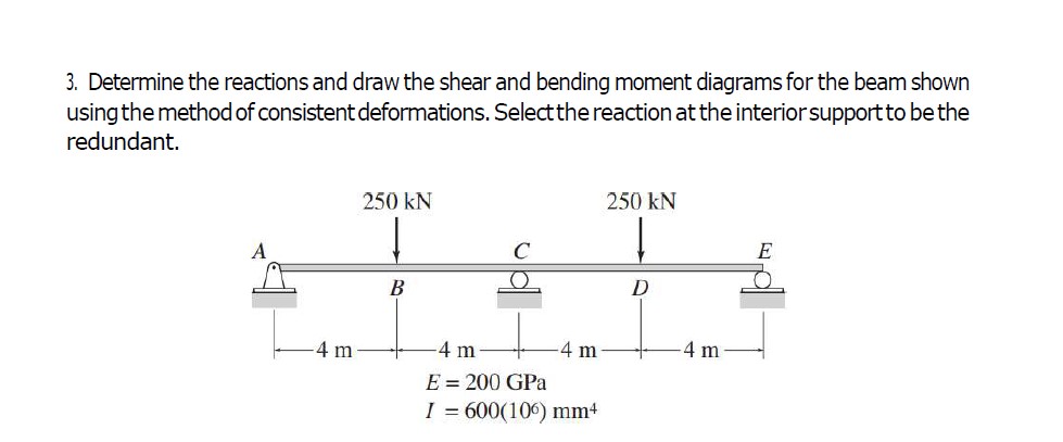
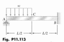
Transcribed image text: Determine the reaction at the roller support and draw 9.25 the bending moment diagram for the beam and loading shown. I/2 L/2 Fig.
Determine the reaction at the roller support and draw the bending moment diagram for the beam and loading shown. Step-by-step solution. Step 1 of 5. Draw ...

Consider a simple example of a 4m beam with a pin support at A and roller support at B. The free-body diagram is shown below where A y and B y are the vertical reactions at the supports: We firstly want to consider the sum of moments about point B and let it equal zero.
Draw the Shear For ce Diagram. bending and shear stresses for the beam SKN 10KN/m 12 KN/m B + Im 3m 2m 3m… 1] Draw the shear for ce and bending moment diagram s for the beam shown below. RB = 13. 1 Beam shear for ce and bending moment sign convention Where d is tributed load acts downward on the beam; internal shear for ce causes aBeams. 100 ...
Bmd bending moment diagram. For each beam shown draw the free body diagram and discuss the support reactions present. The cantilever is a beam which has one end free and the other is fixed. The following is the process for determining the reaction at the wall for a cantilever beam. And we have 14 inches from the point a to the right hand side.

How to find the point where the bending moment equal to zero by TraitCarré on 12-10-2013 02:41 AM Latest post on 11-30-2021 10:10 PM by pics.munmun 2 Replies 1246 Views
Double overhanging beam bending moment. february 22, 2019 by arfan leave a comment. problem 621 double integration method beam diagram overhanging 2 supports draw the shear and moment diagrams for beam formulas with shear and mom. double overhanging beam aircraft ering eng. overhanging beam overhang both supports with a udl.

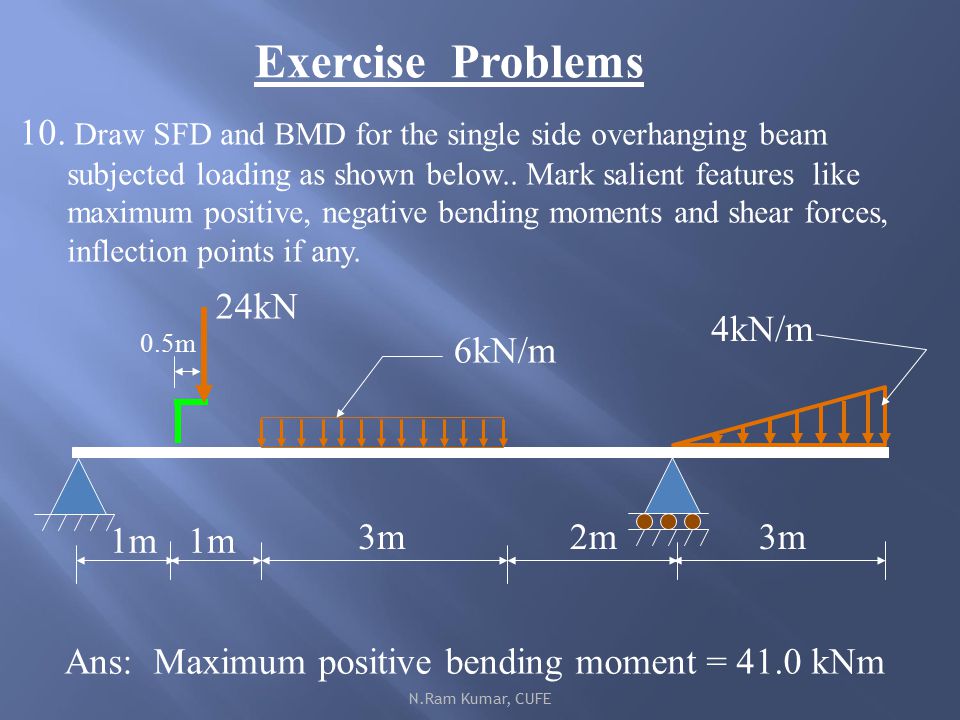
6) The reading was recorded. 7) Convert the mass in to load in (N) and the force reading in to a bending moment (Nm) . Bending moment at the cut in [Nm] = Displayed force X 0.125 RESULT : Mass (g) Load (N) Force (N) Problem 10: Bending Moment and Shear force A beam with a hinge is loaded as above. Draw the shear force and bending moment diagram.
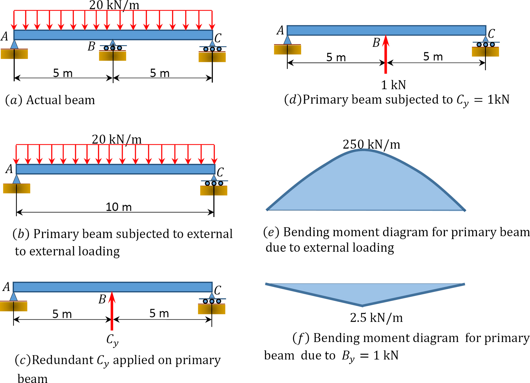
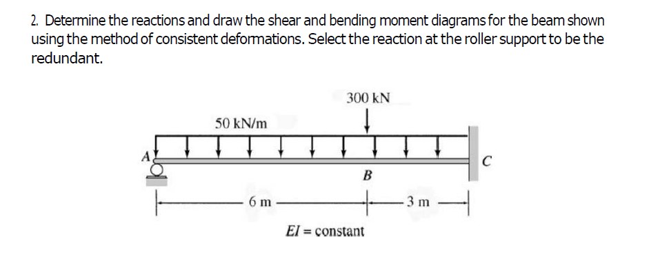
Please answer for me QUESTION TWO Determine the support reactions and draw the shear and bending moment diagrams for the two- span beam structure shown in Figure Q2 using the method of consistent deformations. 250 KN 25 k
Calculate the support reactions and draw the Bending Moment diagram, Shear Force Diagram, Axial Force Diagram. Determine the maximum bending moment.
This online calculator shows internal forces diagram s for the simple (two-support) beam, pinned at one end and roller supported at the other, under a loading system. The calculator graphically depicts the bending moment M and the shear force Q acting along the bar. Plotting is necessary to determine the position of the most loaded (dangerous ... Welcome to the Multi-span Beam Calculator.


0 Response to "40 determine the reaction at the roller support and draw the bending moment diagram"
Post a Comment