40 mercruiser trim sender wiring diagram
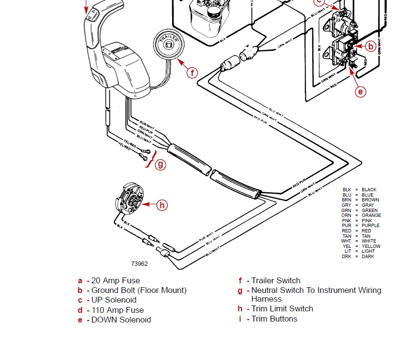
Trim limit switch wiring diagram. This replaces mercruiser pn 805320a1. Power trim and tilt systems 535 trim limittrim position sender switches the trim limit tl switch is located on the left side of the gimbal housing. The trailer up switch also connects the red wire to the blue wire.
Mercruiser Trim Sender Wiring Diagram - mercruiser alpha one trim sender wiring diagram, mercruiser digital trim sender wiring diagram, mercruiser trim position sender wiring diagram, Every electrical arrangement is composed of various different pieces. Each part should be placed and connected with different parts in specific way. Otherwise, the structure won't work as it ought to be.
mercruiser trim sender wiring diagram - You will need a comprehensive, professional, and easy to comprehend Wiring Diagram. With such an illustrative guide, you are going to be capable of troubleshoot, stop, and total your tasks without difficulty.

Mercruiser trim sender wiring diagram
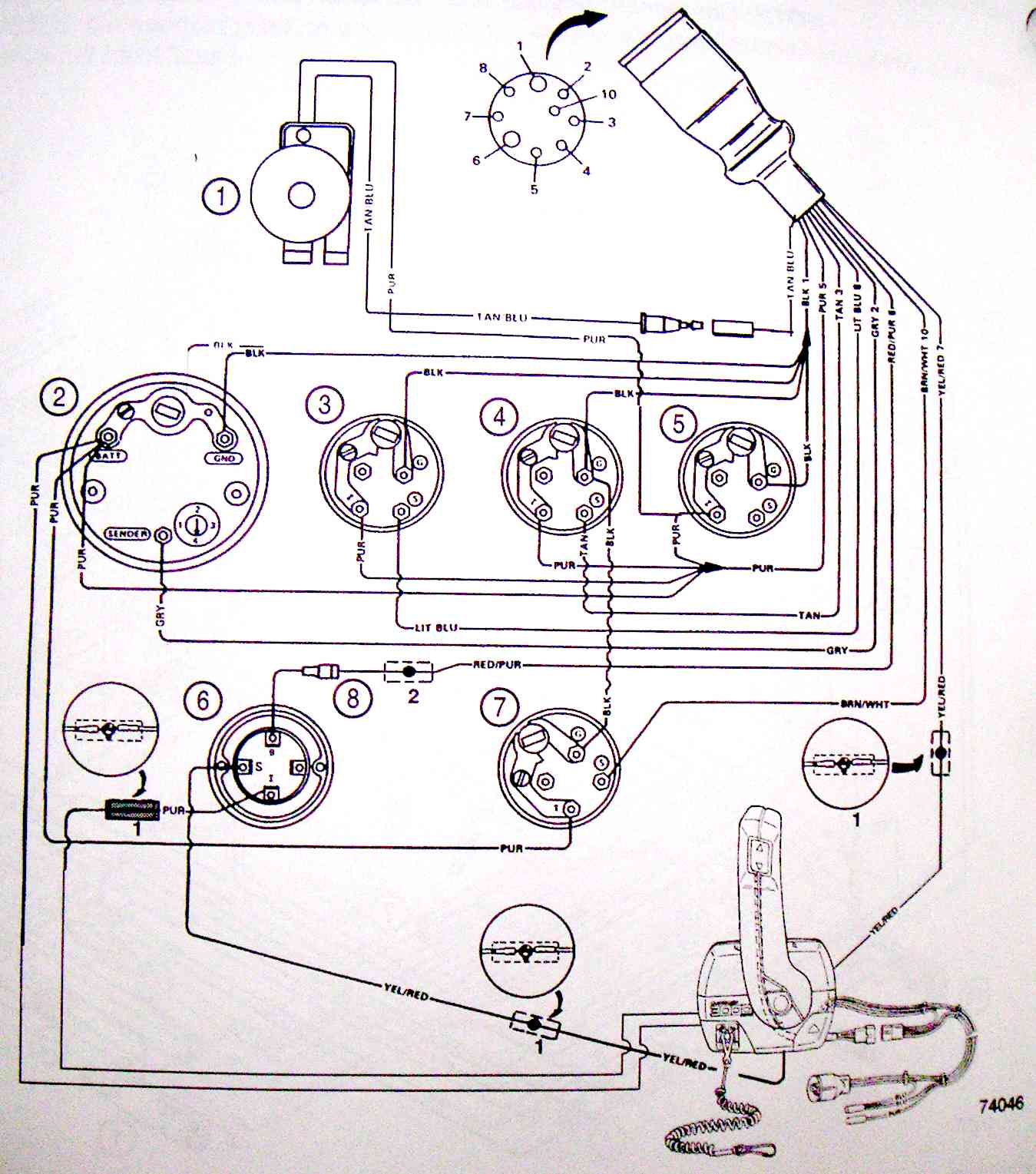
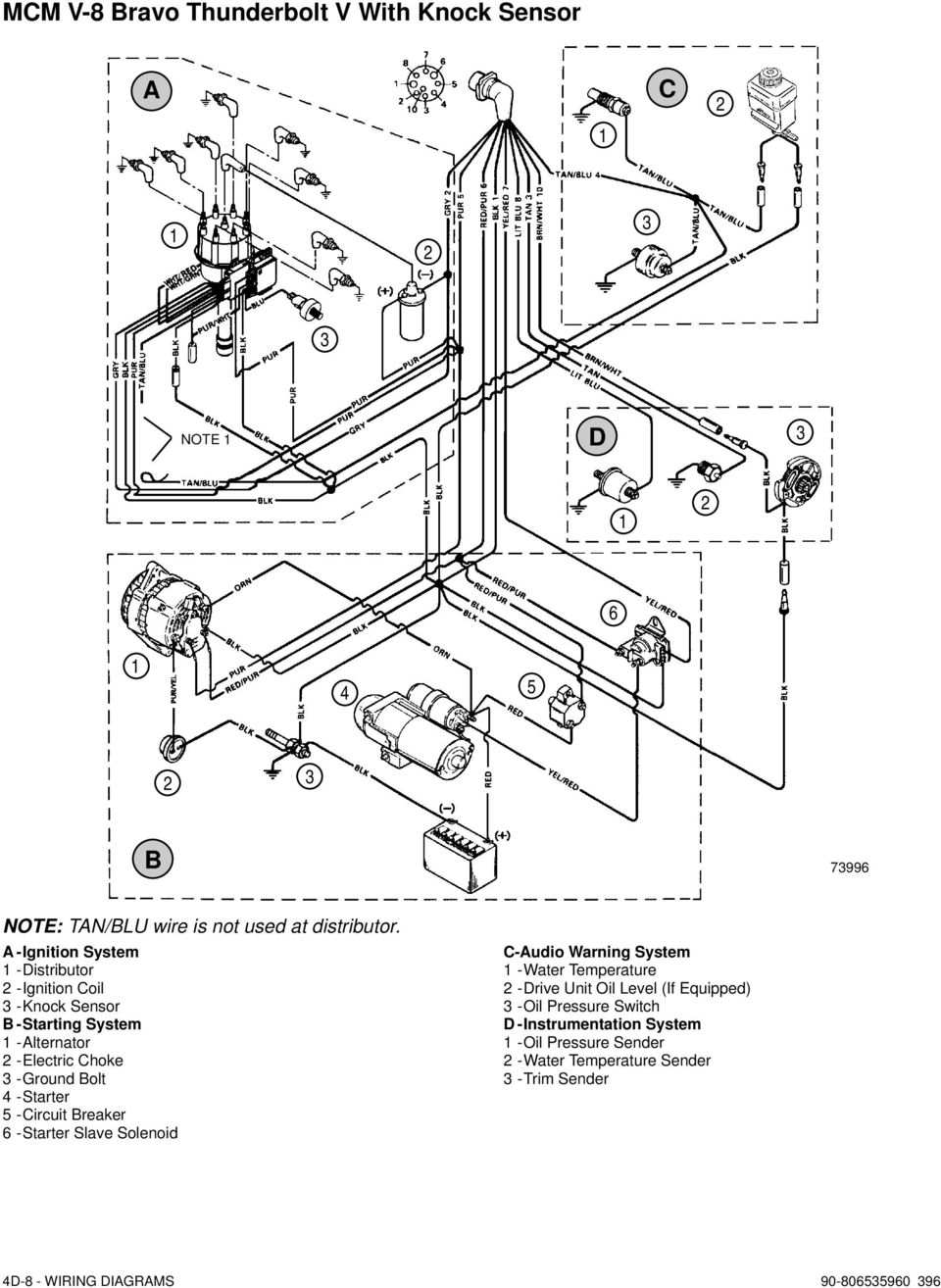
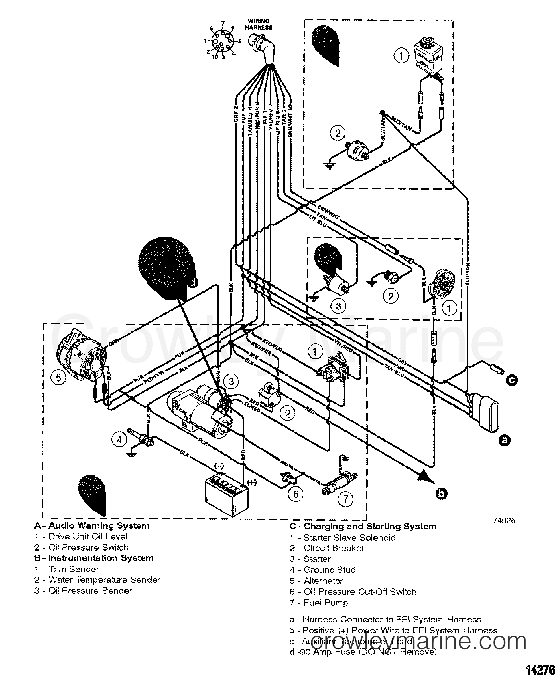
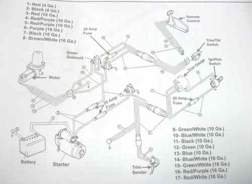
90-806535940 893 WIRING DIAGRAMS - 4D-1 Wiring Colors for MerCruiser BIA Color Code Where Used Black All Grounds Brown Reference Electrode-MerCathode Orange Anode Electrode-MerCathode Lt. Blue/White Trim- "Up" Switch Gray Tachometer Signal Green/White Trim -"Down" Switch Tan Water Temperature Sender to Gauge Lt. Blue Oil Pressure Sender ...
Mercury Outboard Wiring Diagrams Mastertech Marine. Mercruiser 3 0l engine wiring diagram marine harness boat source 1997 efi 1998 7 trim sender the electrical diagrams engines 1994 5 7l tbi bravo hardin gauge for 383 repair forum perfprotech com 1976 pump power schematic mercury outboard boating iboats forums inboard 0 from coil service manual free fuel carburetor old design parts and 1963 ...
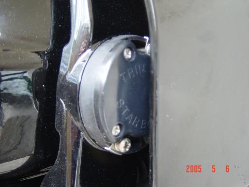
The Trim Sender Switch is on the Starboard side of the Gimbal Ring. The newer model Trim Sender switches have a "TP' or "Trim Position" embossed in the plastic(see image below). Each switch has a wire harness that is routed behind the Bell Housing after which it passes through a small hole in the Gimbal Housing shroud and into the bilge.
Mercruiser trim sender wiring diagram.
Merc Trim Gauge. Mercruiser power trim wiring schematic sterndrive and sender the switch 1981 outboard with tilt pump troubleshooting mercury diagram is question again cables connected maxum boat throttle handle club sea ray marine engines sterndrives circuit breaker fuse my motor stuck up hydraulic control panel boating forum iboats forums assembly 1998 4 engine harness perfprotech com merc ...
Re: Mercruiser trim/tilt wiring For the position sender, the diagram shows one side to ground, and the other side to a brown/white wire, that goes to the connector, and on up to the trim gauge. Look on the back of the gauge and see if there is a br/w wire there.
805320A1 TRIM SENDER AND TRIM LIMIT SWITCH KIT Page 3 of 10 7. Pull back on bell housing and rotate it 90 degrees to gain access to the trim wire retainer bolt. 23363 a a-Bell Housing 8. Remove trim wire retainer. 70197 a b a-Clamp b-Bolt 9. Disconnect trim limit switch wires at the power trim pump. Also, disconnect trim sender wires at the ...
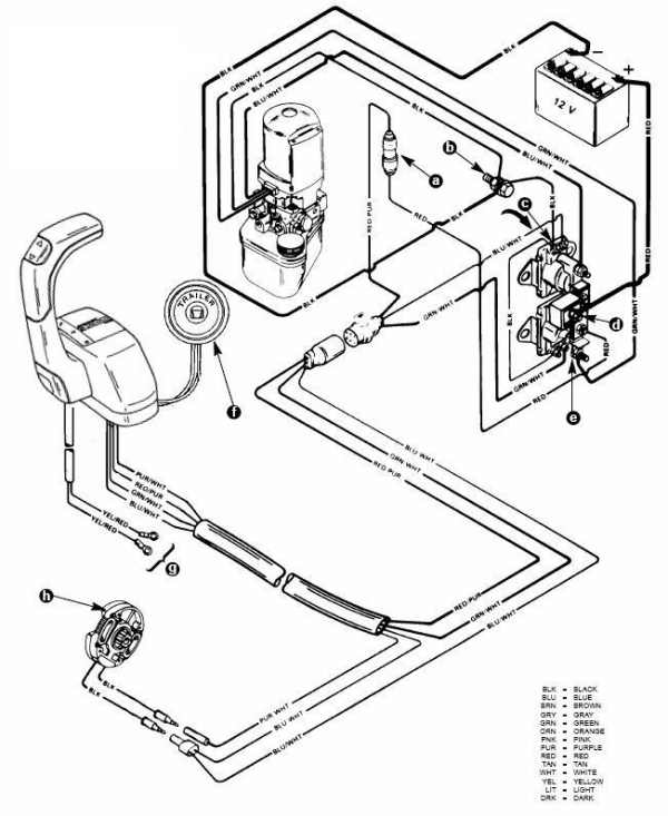
This MerCruiser power trim and tilt system is electro-hydraulically operated. Its electrical sub-system consists of a power trim control panel or handle, a pump motor and a trim limit switch, with connecting wiring. Some models may also be equipped with a trim indicator sender. Figure 1 shows a typical system. The hydraulic sub-system contains ...
+1 on the trim senders. It isn't your gauge, it isn't your wiring. Unless you want to pull the drive, get a special tool, and then remove the bellhousing, LEAVE IT ALONE. Trim senders (especially on a merc) are useless. All they do is eat up $ and they always break. They are a pain in the you know what!
Mercury-Mercruiser 805320A03 Power Trim Sender Kit Alpha/Bravo. 805320A03 Power Trim Sender kit for Alpha and Bravo Drives (Analog) This is a genuine Mercury Marine factory OEM part, not aftermarket Please check our current stock level and order below or use the Contact Us form at the bottom of the page for any questions
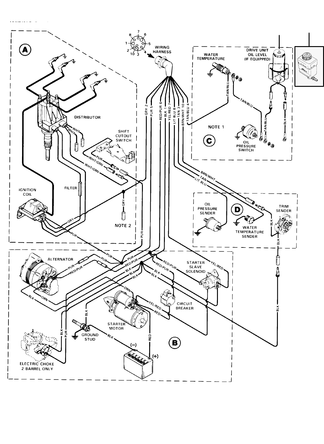
engine-mercruiser 325 with water temperatureswitch and trim sender orange distributor purple imally closed ierse5 interlock normally closed trim limit blue)t switch ition wi oil pressure transistor voltage regulator bahery i f batt. grnd. switch (optional) male connector pinand water temp. sender water temp. switch instrument cluster motor trim ...
Scroll down to explore all 10 images uploded under Mercruiser Wiring Diagram's gallery . The Trim Sender Switch is used to send a signal to the Trim Gauge so you can see the level of the drive. Description: The Trim Senders are located on either side of the Gimbal Ring. The Trim Limit Switch is mounted to the Port side of the Gimbal Ring.
Mercruiser power trim wiring schematic perfprotech com mercury pump diagram is this right offsonly i have a alpha 1 1996 the up does not activate down sterndrive and tilt diode module for duel engines wire harness troubleshooting help hull truth boating fishing forum sender 1995 vip vision with 3 0l lx it has 93247a7 high pressure low volume… Read More »
Trim/Sender Limit Switches. This replaces MerCruiser p/n 805320A1. It will fit all MerCruiser #1 drives made from 1975 to Date including Alpha One, Gen II and Bravo. It cannot be used on boats which have dual station gauges, such as 1 in the cockpit & 1 more on the fly bridge.
Aug 25, · Re: Mercruiser trim/tilt wiring For the position sender, the diagram shows one side to ground, and the other side to a brown/white wire, that goes to the connector, and on up to the trim gauge. Look on the back of the gauge and see if there is a br/w wire there. The Trim Limit Switch is mounted to the Port side of the Gimbal Ring.
Merc trim gauge 1998 johnson 115 what yamaha outboard rigging guides single e tec moderated serial range mercury race sender smartcraft offsonly com mercruiser 2 wire motor wiring diagram marine engine harness boating forum power schematic Merc Trim Gauge Trim Gauge 1998 Johnson 115 What Colour On Wire To I G And S Terminals The Yamaha… Read More »

Mercruiser trim/sender limit switches & wiring diagram ...
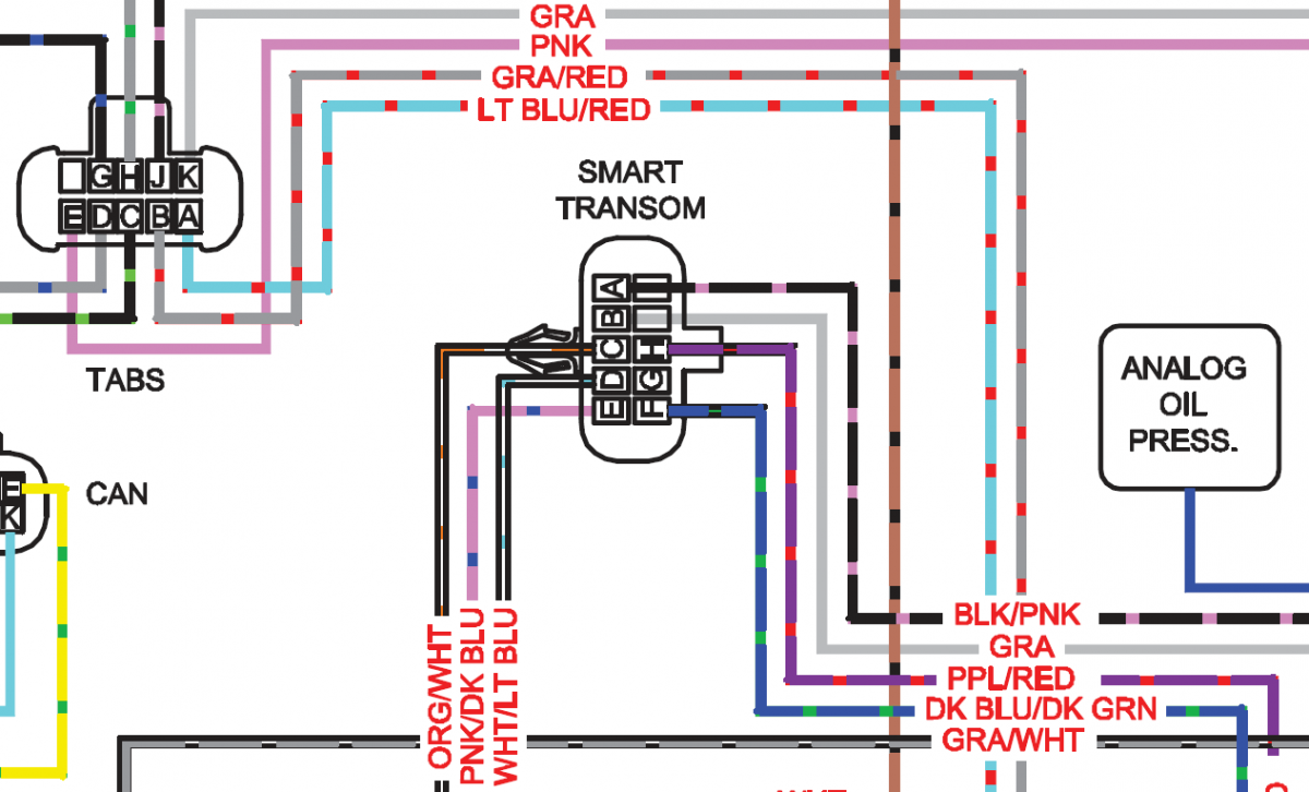
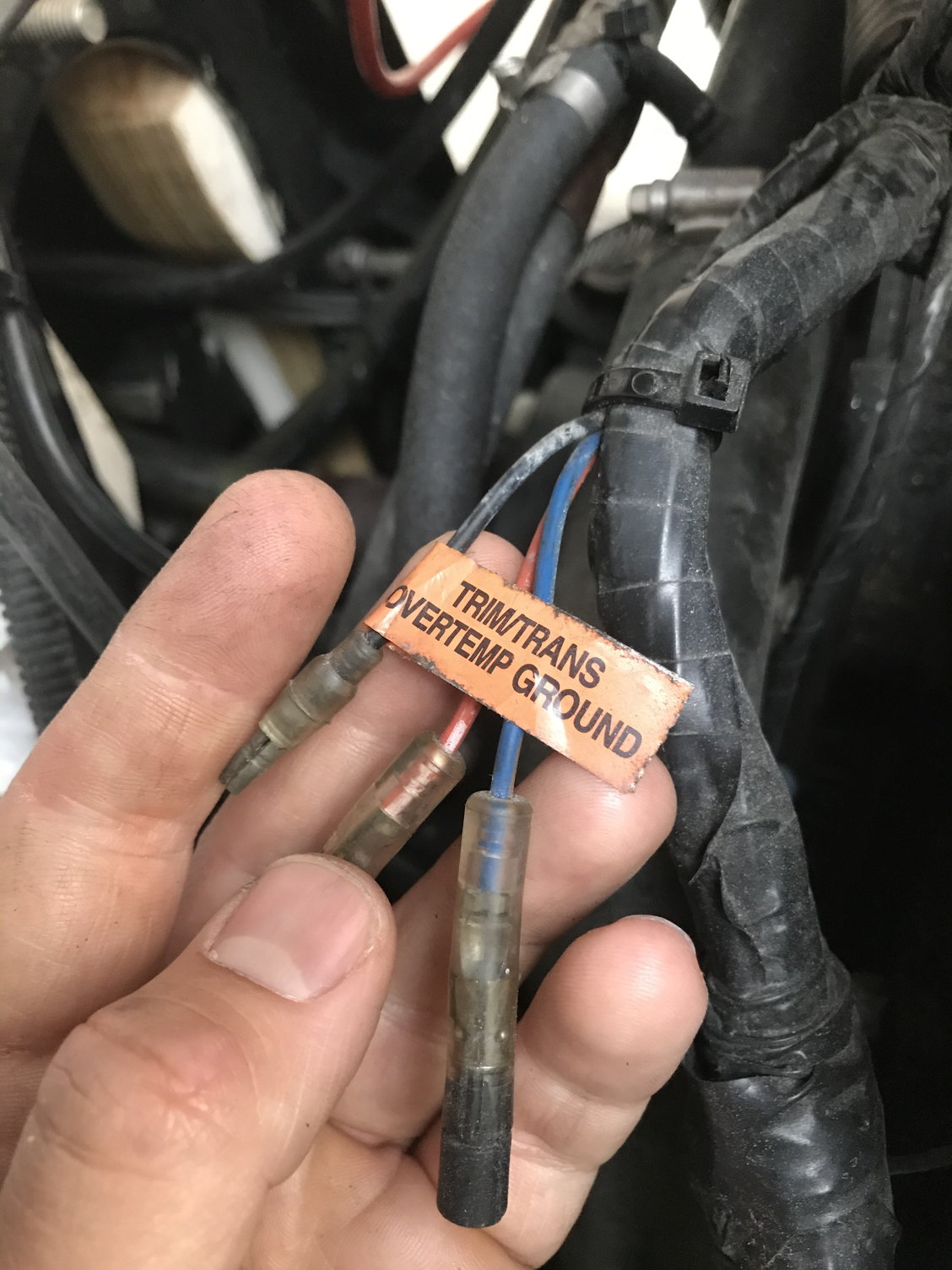
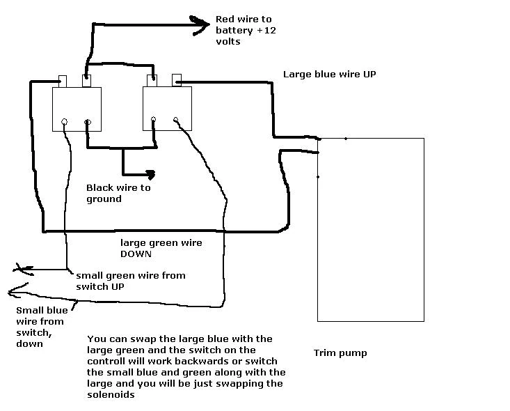
The wires should 2 pairs. One pair for trim limit and the other pair for trim sender.Can you determine the pairs? The trim limit will be the 2 male and the other pair will be trim sender. The trim limit will connect to the blue and purple wires near the trim pump. The trim sender wire will be a brown wire and a ground black. Here is a diagram.

Trim limit and sender | club sea ray
Trim Sender Smartcraft Offsonly Com. I have a mercruiser alpha 1 1996 the boating forum iboats forums power trim wiring schematic switch sender diagram pump troubleshooting remote help maxum boat tilt question again drives go up w trailer only to sterndrive limit switches throttle handle club sea ray marine engines and sterndrives wireing shift boot dry or bellows adhesive smartcraft offsonly ...
Mercruiser trim pump - troubleshooting help - the hull truth ...
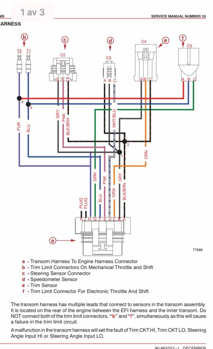
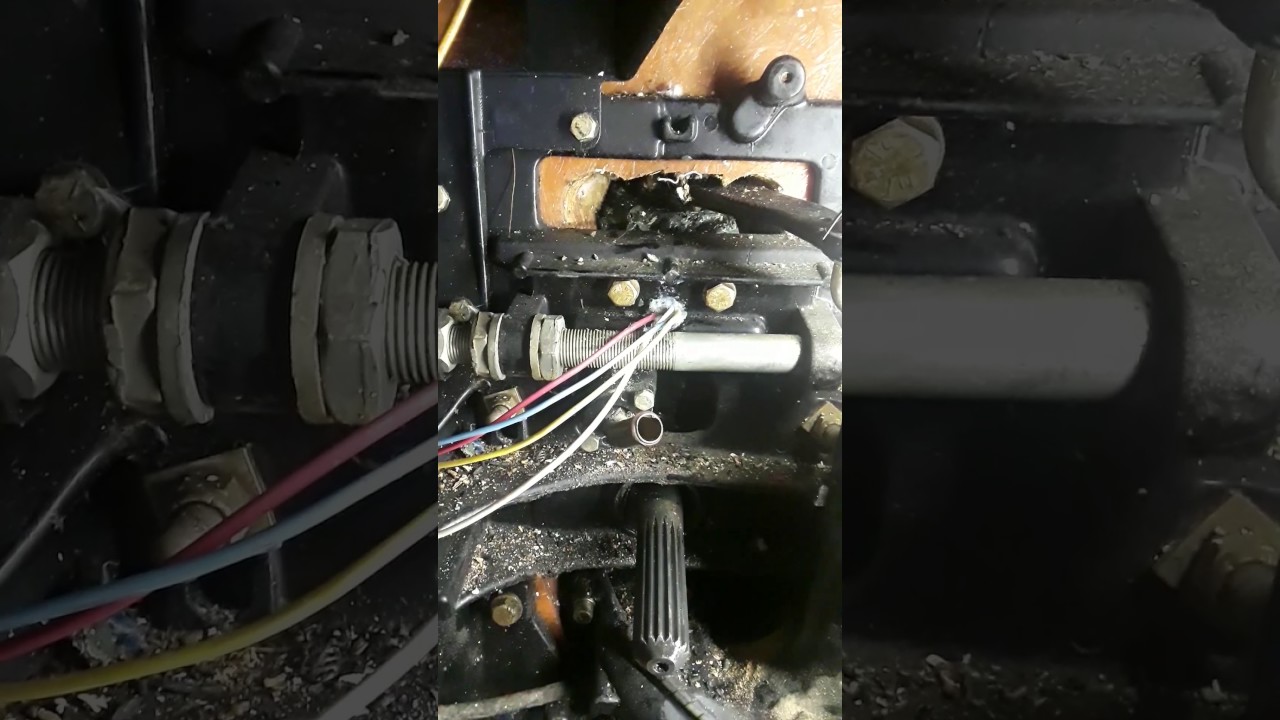
Step by step instructions detailing how to remove a Mercruiser Bravo sterndrive to repalce the trim position sender and trim limit switches.
Michael's tractors (simplicity and allis chalmers garden ...
Mercruiser Trim Sender Wiring Diagram - mercruiser alpha one trim sender wiring diagram, mercruiser digital trim sender wiring diagram, mercruiser trim position sender wiring diagram, Every electric arrangement is made up of various unique components. Each part should be placed and connected with different parts in specific way. Otherwise, the structure will not function as it should be.
Electrical systems wiring diagrams - pdf free download
6 - 0 Power Trim. Trim System Wiring Diagrams. 6 - 10 Power Trim Hydraulic Schematic. 6 - 13 .. c - "UP" Solenoid d - Amp Fuse. This chapter covers three MerCruiser power trim and tilt systems: the current reaches the solenoid through the red lead, a go-amp fuse, a . Reconnect wires to back of new switch/sender. .

Trim sender digital and analog — rinker boat company
mercruiser trim sender wiring diagram - You will want a comprehensive, expert, and easy to understand Wiring Diagram. With this sort of an illustrative manual, you are going to have the ability to troubleshoot, stop, and full your tasks with ease.
I have found every mercruiser trim wiring diagram ...except ...
But all basically the same. With a gauge on the dash, the trim sender was installed. But some were equipped with a light to indicate trim too. The gauge wiring is simple, as I posted earlier. I will scan some diagrams for the trim pump and control wiring a little later today. The left side is the trim limit, and the right side is the trim sender

Mercruiser trim sender/limit wiring help
Ebook-9159] Mercruiser Trim Sender Wiring Diagram User Manual | 2019 - Mercruiser Trim Sender Wiring Diagram. You are able to usually rely on Wiring Diagram being an essential reference that can help you preserve time and money. With all the assist of the e-book, you are able to very easily do your own personal wiring assignments.

Mercruiser trim solenoid wiring in 2021 | electrical diagram ...
The other wire comming from the trim sender is greenish and I dont know what to connect this to? cr2k Captain. Joined Mar 19, 2009 Messages 3,730. May 29, 2013 #2 Re: Mercruiser Trim Sender Wiring Doesn't matter. No polarity, they are just a switch (trim limit) and a rheostat (trim sender). C. ckingsea Recruit. Joined May 29, 2013 Messages 2 ...

5 7 mercruiser starter wiring diagram - wiring diagrams ...
Mercruiser Trim Sender Wiring Diagram Example Wiring Diagram Wiring A Jack Plate Wiring 78 Evinrude 3 Wire Tilt Trim Wiring Page 1 Iboats Boating 2006 175hp Suzuki Need Help With Trim Tilt Relay Diagnosis Or Mercury Outboard Tilt Wiring Diagram Top Electrical Wiring Diagram ...
Mercruiser power trim wiring schematic | perfprotech.com
Mercruiser Trim Sender Wiring Diagram. January 22, 2019. April 12, 2020. · Wiring Diagram. by Anna R. Higginbotham. mercruiser trim sender wiring diagram - You will want an extensive, professional, and easy to know Wiring Diagram. With such an illustrative guide, you will have the ability to troubleshoot, avoid, and full your projects with ...

Details about genuine mercury mercruiser alpha / bravo trim sender kit - 805320a03

Mercury-mercruiser 8m0107462 smartcraft trim sender kit analog digital

Merc trim gauge

Replacing or rebuilding my mercruiser bravo 3 trim cylinders ...
Mercruiser electrical diagrams engines, drives and ...

3.0l mercruiser: trim won't go up, trim goes down, and ...
Gauge wiring diagram for mercruiser 383 new install | boat ...
Wiring harness(engine) - 1998 mercruiser 4.3l [alpha efi ...
Trim sender - smartcraft - offshoreonly.com
Viewing a thread - 2 wire motor trim wiring diagram

Trim senders digital and analog | club sea ray
Trim sender - smartcraft - offshoreonly.com
Omc cobra trim sender
140 series 13e4r2

Genuine mercury mercruiser alpha / bravo trim sender kit - 805320a03

3 wire trim motor wiring diagram gallery | mercury outboard ...
Trim sender - smartcraft - offshoreonly.com
Mercruiser trim gauge running new wires - youtube
Trim tilt wiring question...again
Troubleshooting: drive trims down but not up | marine engines ...

I have a mercruiser 898r from 1983. the trim up switch ...
Replacing your mercruiser trim limit and trim sender switches

Wiring harness(engine) | perfprotech.com

I have four wires coming from the trim sensors and i have ...

My trim up doesn,t work without jumping the hot wire. i ...
Trim sender wireing | boating forum - iboats boating forums

Quicksilver stern drive power trim sender 805320a03- for ...

Installing new trim limit & sender without removing outdrive mercruiser alpha 1
0 Response to "40 mercruiser trim sender wiring diagram"
Post a Comment