42 cu ni phase diagram
pressure to be constant at one atmosphere. Phase diagrams for materials with more than two components are complex and difficult to represent. An example of a phase diagram for a ternary alloy is shown for a fixed T and P below. Phase diagrams for binary systems ternary phase diagram of Ni-Cr-Fe
English: Cu-Ni phase diagram. Polski: Wykres fazowy Cu-Ni. Date: 28 March 2011: Source: Own work: Author: Joanna Kośmider: Permission (Reusing this file) Public domain Public domain false false: I, the copyright holder of this work, release this work into the public domain. This applies worldwide.
There is two types of important phase diagrams are used one is a slow process diagram, and another is a fast process diagram. Answer and Explanation: 1 Phase diagram of the Ni-Cu is
Cu ni phase diagram
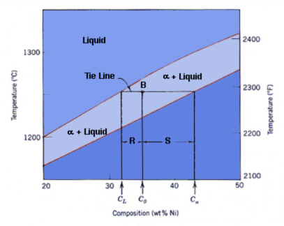
Introduction to the Cu-Ni phase diagram relating to the use of the Lever Rule for determining composition and phase weight percentages.
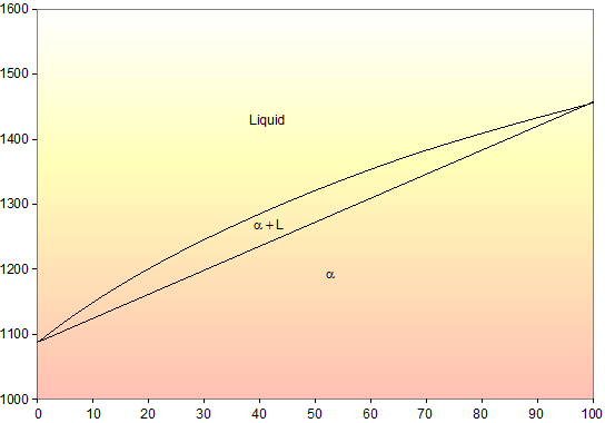
We have examined isomorphous phase diagrams, and used the example of the Cu-Ni phase diagram. In this module we will examine eutectic phase diagrams. A eutectic system has two components, and they have limited solubility. Upon cooling, the liquid will transform into two mixed solid phases. We will use the Pb-Sn phase diagram as an example.
In this work, phase relations and thermal stabilities of equilibrium phases in the Cu-Ni-S system have been reviewed. The calculated phase diagram of Cu-N system has been validated. At T > 630 K, in the N-rich corner, large scatter in data has been observed and discussed in detail.
Cu ni phase diagram.
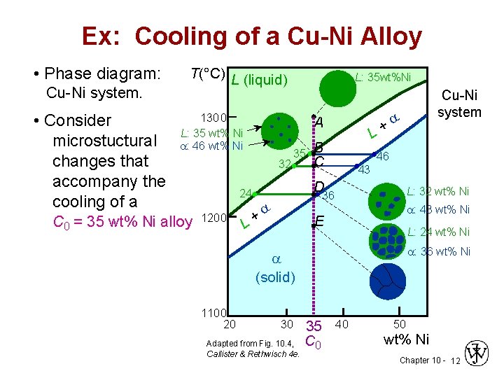
Shown below is the Cu-Ni phase diagram (Figure 9.3a) and a vertical line constructed at a composition of 70 wt% Ni-30 wt% Cu. (a) Upon heating from 1300°C, the first liquid phase forms at the temperature at which this vertical line intersects the α-(α + L) phase boundary--i.e., about 1345°C.
Move the mouse over the phase diagram to view temperature and composition at any point. View micrographs for the Cu-Ni system. List all systems with phase diagrams
Al-Cu-Ni PHASE DIAGRAM This phase diagram is helpful in the analysis of 2618-type heat-resistant alloys and 339.0-type piston alloys that contain nickel, copper, and other alloying components (Tables 7.1 and 7.2). The ternary Al7Cu4Ni phase forms in the aluminum corner of the Al-Cu-Ni system.
The thermodynamic calculation of phase equilibria in the Cu-Ni-Si alloy system was carried out using the CALPHAD method. The calculations show that there are three two-phase areas and two three ...
Shown below is the Cu-Ni phase diagram (Figure 9.3a) and a vertical line constructed at a composition of 70 wt% Ni-30 wt% Cu. (a) Upon heating from 1300°C, the first liquid phase forms at the temperature at which this vertical line intersects the α-(α + L) phase boundary--i.e., about 1345°C. )-)-
Part of the phase diagram of the Cu-Ni-Mn system from 0 to 20% Ni and from 30 to 50% Mn is refined with the help of a theoretical analysis and based on the experimental data.
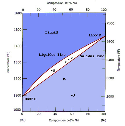
Cu-Ni phase diagram A(1100, 60): 1 phase: B(1250, 35): 2 phases: L + Determination of phase(s) present Melting points: Cu = 1085°C, Ni = 1453 °C Solidus - Temperature where alloy is completely solid. Above this line, liquefaction begins. Liquidus - Temperature where alloy is completely liquid. Below this line, solidification begins.
This video explains binary phase diagrams, specifically the Cu-Ni System. For further studies: visit https://www.doitpoms.ac.uk/tlplib/phase-diagrams/printal...
Example: Cu-Ni phase diagram (only for slow cooling conditions) Liquidus line: the line connecting Ts at which liquid starts to solidify under equilibrium conditions Solidus: the temperature at which the last of the liquid phase solidifies Between liquidus and solidus: P =2. Chapter 8 9
EN380 Homework #6 Solution 1.The binary (two-component) phase diagram for copper-nickel alloys is shown below. A Cu - Ni alloy contains 30 wt. % Cu at a temperature of 1350 C. Find the following: (a)melting point for pure copper.1084 C (b)melting point for pure nickel.1455 C (c)wt. % Niin the (entire) binary alloy.70% Ni
Phase Diagrams • Indicate phases as function of T, Co, and P. • For this course:-binary systems: just 2 components.-independent variables: T and Co (P = 1 atm is almost always used). • Phase Diagram for Cu-Ni system Adapted from Fig. 9.3(a), Callister 7e. (Fig. 9.3(a) is adapted from Phase Diagrams of Binary Nickel Alloys , P. Nash
金属やセラミックスの状態図、エンリンガム図などの情報を提供しています。 一部、不確かなものもありますので、自己 ...
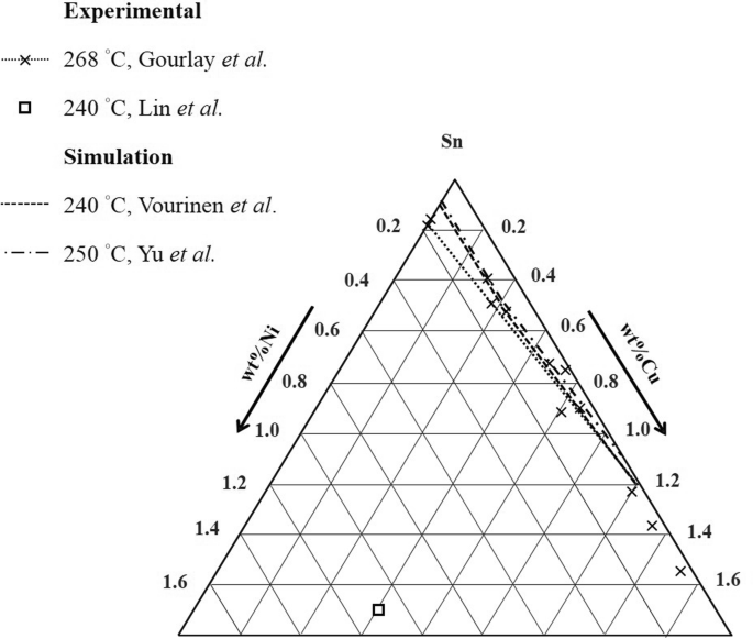
Experimental determination of the sn-cu-ni phase diagram for ...
Cu-Ni Phase Diagram 1000 1200 1400 1600 26% 36% 50% 62% 1260 (°C) Cu Ni Liquid Solid L+S Substitutional Solid Alloys Pure Metals Pure Metals Time T Time T Time L S 4 Pb-Sn Phase Diagram Pb (lead) Sn (Tin) Temperature, °F 0 100 200 300 400 500 600 α α+L L β+L β α+β 362 °F 61.9% Sn Eutectic Composition and Temperature Time α 5 Fe-C ...

A 65 wt% ni-35% cu alloy is heated to a temperature within ...
The density of copper (8.93 kg/dm 3 at 20 °C) varies only slightly with increasing nickel content (density of nickel at 20 °C = 8.9 kg/dm 3) and is 8.9 kg/dm3 for all Cu-Ni alloys specified in DIN 17 664. This aspect can also be seen in Table 7 with the physical properties of the Cu-Ni resistance alloys to DIN 17 471.
Phase diagram for cu-ni
Phase diagrams 0 20 40 60 80 100 wt% Ni 1000 1100 1200 1300 1400 1500 1600 T(°C) L (liquid) α (FCC solid solution) L α s s Cu-Ni phase diagram • Rule 1: If we know T and C o, then we know:--the # and types of phases present. • Examples: Adapted from Fig. 9.3(a), Callister 7e. (Fig. 9.3(a) is adapted from Phase Diagrams of Binary Nickel ...

Materials science: tutorials
Phase Diagrams • Indicate phases as a function of T, C, and P. • For this course:-binary systems: just 2 components.-independent variables: T and C (P = 1 atm is almost always used). Phase Diagram for Cu-Ni system Fig. 11.3(a), Callister & Rethwisch 9e. (Adapted from Phase Diagrams of Binary Nickel Alloys, P. Nash, Editor, 1991. Reprinted
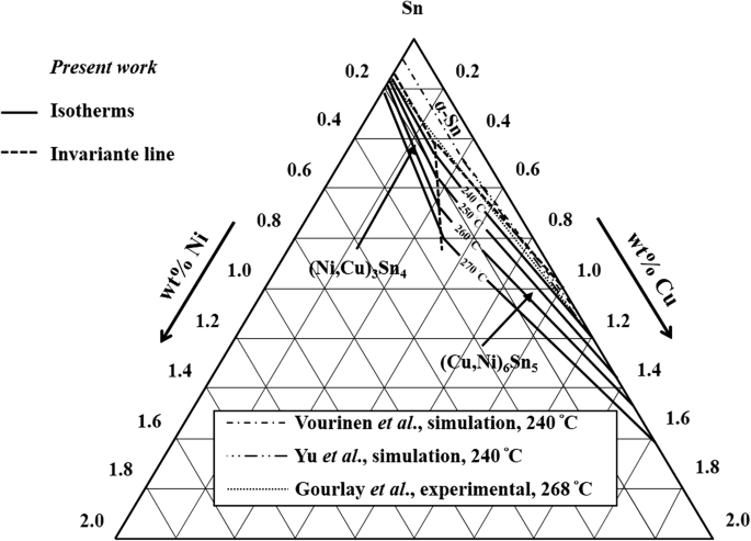
Experimental determination of the sn-cu-ni phase diagram for ...
Section-Editor: Hiroaki Okamoto (Phase Diagrams) Cite this content Pierre Villars (Chief Editor), PAULING FILE in: Inorganic Solid Phases, SpringerMaterials (online database), Springer, Heidelberg (ed.) SpringerMaterials Cu-Ni Binary Phase Diagram 0-24 at.%
Chapter 10 phase diagrams issues to address when
To generate a new Sn-Cu-Ni phase diagram based on reliable experimental data including four liquidus lines at 240 °C, 250 °C, 260 °C, and 270 °C. Characterize the invariant (or invariants) line for the equilibrium between a liquid phase with two IMCs Corroboration of Attainment of Homogeneous Liquid During Fast Quenching

Copper-nickel phase diagram - metallurgical engineering ...
The binary phase diagram shown for the copper-nickel alloy indicates that these materials can form both liquid and solid solutions over the full range of composition from Cu to Ni. Above 1728 K, the melting point of pure Ni the alloys ar in the liquid phase. Between 1728 K and 1357 K (the melting point of Cu) the alloys can be either solid or ...

Solved a phase diagram of cu-ni (binary) system. an alloy ...
Binary phase diagram If a system consists of two components, equilibrium of phases exist is depicted by binary phase diagram. For most systems, pressure is constant, thus independently variable parameters are -temperature and composition. Two components can be either two metals (Cu and Ni), or a metal and a compound (Fe and Fe3C), or two ...

Shinwonmetal co., ltd. ++
diagrams. The binary phase diagram is used for system of two components and its classifications depend on number of phases as; isomorphous contain system with two phases such as Cu - Ni system. The...
Nglos324 - phasediagram
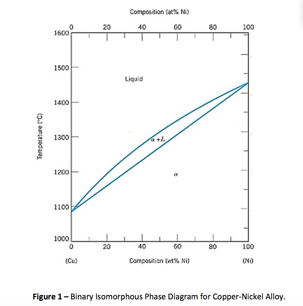
phase diagram of the system, Figure 1203.01.02. Note that, apart from the pure elements, all alloys of Cu and Ni have a range of temperatures over which solidification (freezing) occurs - the field is defined by the liquidus and solidus lines on the phase diagram. We now need to look more closely at the consequences of this.

Mecn 2010: introduction to copper nickel phase diagram
The Cu-Ni and binary phase diagram (Figure 10.3) is the simplest type of binary phase diagrams for two metals. Figure 10.3 shows that Cu and Ni are mutually soluble at room temperature throughout the entire range of compositions. Remember from Chapter 5that we discussed the HumeRothery -
![Cu-Ni phase diagram [2]. | Download Scientific Diagram](https://www.researchgate.net/profile/Andras-Kovacs-5/publication/321224714/figure/fig1/AS:631621728337962@1527601763764/Cu-Ni-phase-diagram-2.png)
Cu-ni phase diagram [2]. | download scientific diagram
Experimental determination of the sn-cu-ni phase diagram for ...
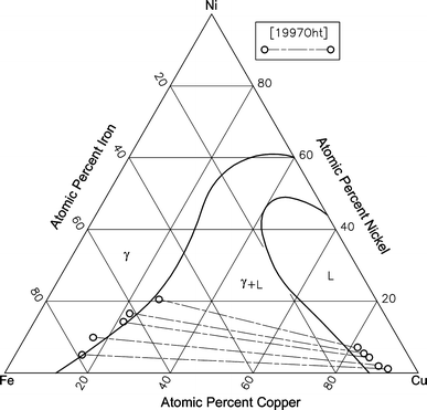
Cu-fe-ni (copper-iron-nickel) | springerlink
Assignment 7 solutions

File:cu-ni-phase-diagram-greek.svg - wikimedia commons
Has the cu-ni phase diagram have any miscibility gap at a ...

Copper–nickel phase diagram including the miscibility gap of ...

Binary phase diagrams in metallurgy - mechanicalbase
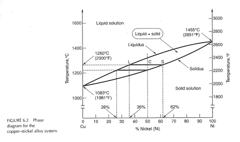
Solved) - for the copper—nickel phase diagram in figure 6.2 ...
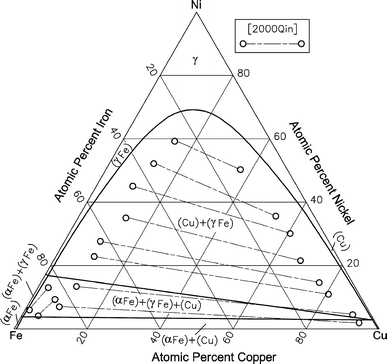
Cu-fe-ni (copper-iron-nickel) | springerlink

A copper-nickel alloy contains 47 wt% cu and 53 wt % ni and ...

Binary phase diagram (temperature versus composition) of bulk ...
![PDF] Cu-Ni-Sn: A Key System for Lead-Free Soldering ...](https://d3i71xaburhd42.cloudfront.net/cfd17952624149800434cbd2148bfd158b8f0565/11-Figure2-1.png)
Pdf] cu-ni-sn: a key system for lead-free soldering ...
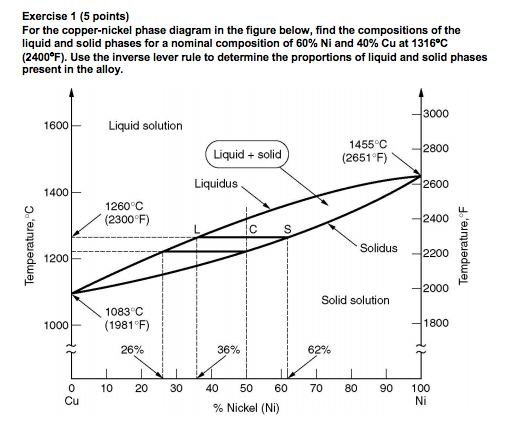
Solved for the copper-nickel phase diagram in the figure ...

Solved using the cu-ni phase diagram shows bleow, to | chegg.com

Binary phase diagrams - cu-ni system | cu-ni phase diagram explained |phase diagram explained

Binary phase diagrams - cu-ni system
The copper-nickel application
Copper-nickel alloys: properties, processing, applications

Influence of ni additions on the viscosity of liquid al2cu

Thermodynamic calculation of phase equilibria in the cu–ni–zn ...

The ni-cu alloy phase diagram. the initial condition of the ...

Figure 3 from the cu-mg-ni (copper-magnesium-nickel) system ...
Chapter 8 phase diagrams

A cu-ni alloy is slowly cooled to 1250 o c. both liquid and ...
Solved question 6: using the cu-ni phase diagram (fig. 1 ...

Thermodynamic calculation of phase equilibria in the cu–ni–zn ...
Cu-ni example

For the copper (cu) nickel (ni) binary phase diagram shown ...

Cu-ni - atdinsdale
0 Response to "42 cu ni phase diagram"
Post a Comment