42 draw a ray diagram representing your experiment from part c
Jan 25, 2017 · Draw a ray diagram representing your experiment from part c. Draw a ray diagram. Yet the same method works for drawing a ray diagram for any object location. Step by step method for drawing ray diagrams. Complete the diagram by adding the incident ray. The dashed line represents the normal to the surface between the water and the diamond. Click here👆to get an answer to your question ️ (a) Draw ray diagram of refraction of light through a prism and explain the phenomenon of dispersion of light.(b) Write the formula for lens power and define its unit.
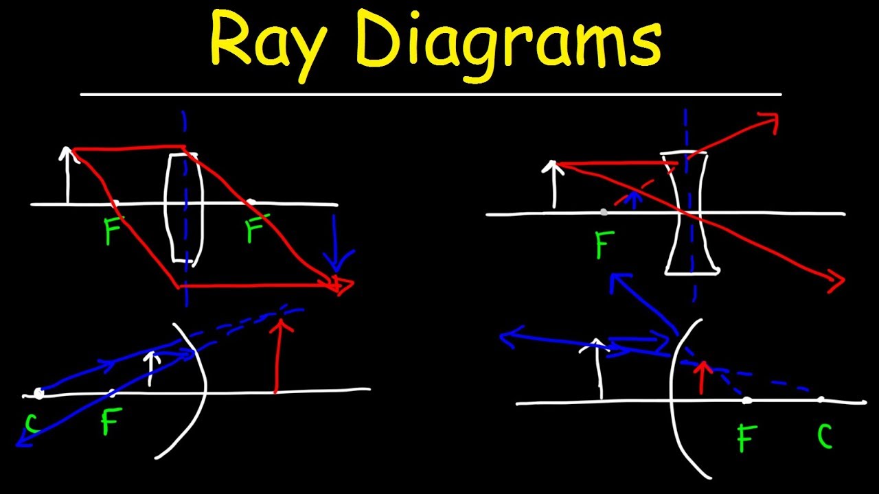
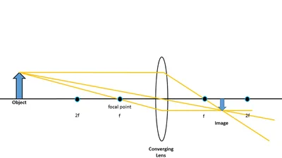
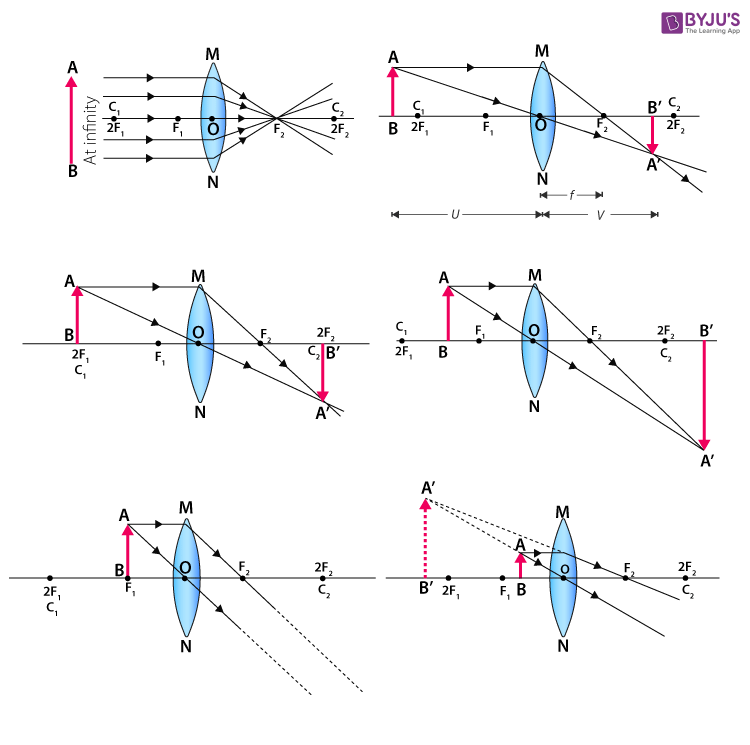
Step-by-Step Method for Drawing Ray Diagrams. The method of drawing ray diagrams for double convex lens is described below. The description is applied to the task of drawing a ray diagram for an object located beyond the 2F point of a double convex lens. 1. Pick a point on the top of the object and draw three incident rays traveling towards the ...
Draw a ray diagram representing your experiment from part c
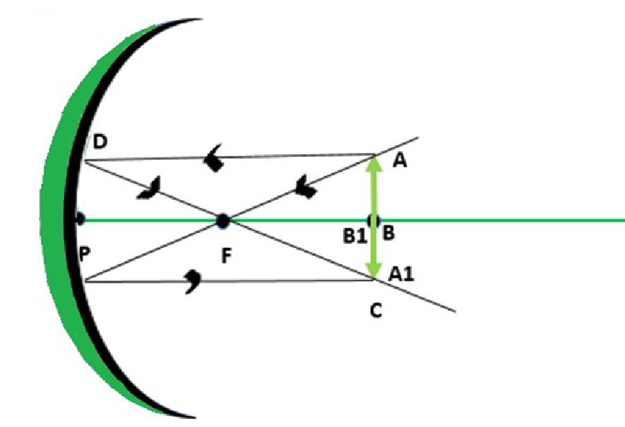
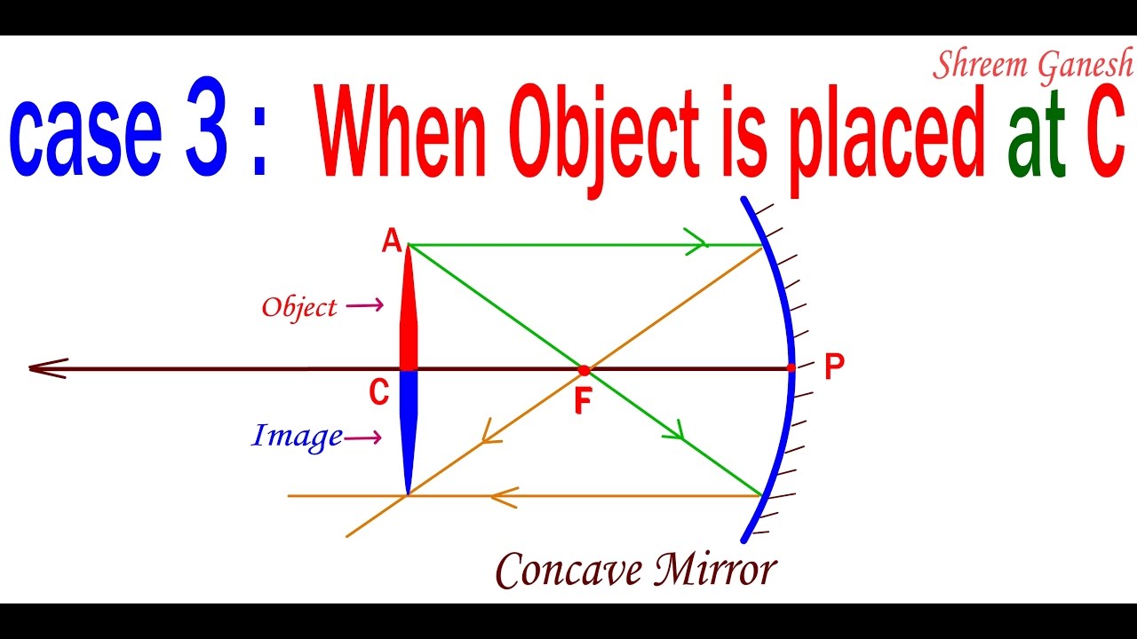
Depending on the position of the object you may need to draw a line from the object through C to get to the mirror or, as is the case here, draw a beam from the object which doesn't pass through C on its way to the mirror but when reflected straight back along this path will pass through C. Here this ray passes from the object to the mirror, directly away from C (the dashed line is a construction line added to make the diagram clearer, it does not represent the path of a ray). A real image is an image that can be projected onto a screen. A virtual image appears to come from behind the lens. To draw a ray diagram: Draw a ray from the object to the lens that is parallel ... May 30, 2018 · In such cases it is customary to draw rays for the extreme positions of such objects. Shows how to draw ray diagrams to locate the image formed by a convex lens. Refraction Geometrical Optics Siyavula Step by step method for drawing ray diagrams. Draw a ray diagram representing your experiment from part c. Drawing ray diagrams a step by step ...
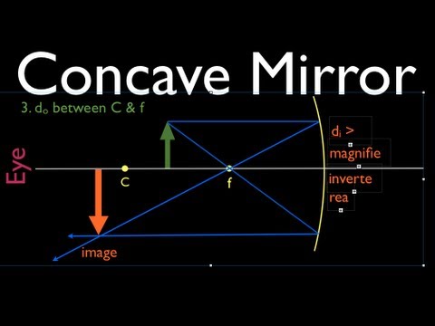
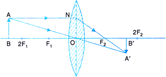
Draw a ray diagram representing your experiment from part c. Here, Object AB is beyond 2F 1. First, we draw a ray parallel to principal axis. So, it passes through focus after refraction. We draw another ray which passes through Optical Center. So, the ray will go through without any deviation. Where both rays meet is point A'. And the image formed is A'B'. This image is formed between F 2 and 2F 2. The theme of this unit has been that we see an object because light from the object travels to our eyes as we sight along a line at the object. Similarly, we see an image of an object because light from the object reflects off a mirror and travel to our eyes as we sight at the image location of the object. From these two basic premises, we have defined the image location as the location in space where light appears to diverge from. Ray diagrams have been a valuable tool for determining the path taken by light from the object to the mirror to our eyes. In this section of Lesson 3, we will investigate the method for drawing ray diagrams for objects placed at various locations in front of a concave mirror. Drawing ray diagrams for plane mirrors. Refraction of light. Total internal reflection. This is a short tutorial on how to draw ray diagrams for plane mirrors. Click on the images to view a larger version. Initially, we have an object in front of a plane mirror. Your diagram should have three rays center of lens and both focal points coming from the top of the object. Draw a ray diagram representing your experiment from part c. Assume the object is in focus. The method is applied to the task of drawing a ray diagram for an object located beyond the center of curvature c of a concave mirror.
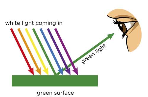
Ray diagrams help us trace the path of the light for the person to view a point on the image of an object. Ray diagram uses lines with arrows to represent the incident ray and the reflected ray. It also helps us trace the direction in which the light travels. Plane Mirror vs Spherical Mirrors Express your answer in centimeters. View Available Hint(s) dod o d_o = cm The convex mirror is now replaced by a concave mirror with the same radius of curvature. Part C Consider the following diagrams, where now C and F represent, respectively, the center of curvature and the focal point of the concave mirror. Drawing Ray Diagrams - a Step-by-Step Approach. This section of Lesson 2 details and illustrates the procedure for drawing ray diagrams. Let's begin with the task of drawing a ray diagram to show how Suzie will be able to see the image of the green object arrow in the diagram below. For simplicity sake, we will suppose that Suzie is viewing the ... A ray diagram shows the path of light from an object to mirror to an eye. A ray diagram for a convex mirror shows that the image will be located at a position behind the convex mirror. Furthermore, the image will be upright, reduced in size (smaller than the object), and virtual. This is the type of information that we wish to obtain from a ray diagram.
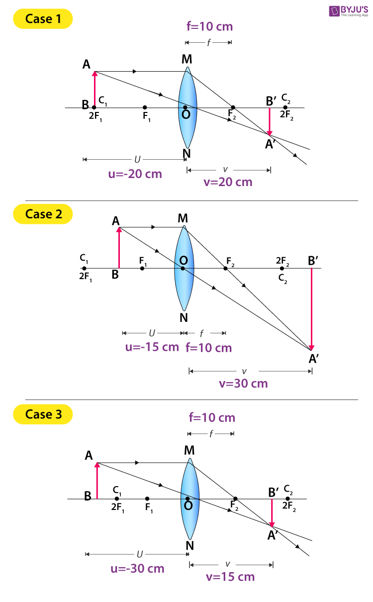
May 30, 2018 · In such cases it is customary to draw rays for the extreme positions of such objects. Shows how to draw ray diagrams to locate the image formed by a convex lens. Refraction Geometrical Optics Siyavula Step by step method for drawing ray diagrams. Draw a ray diagram representing your experiment from part c. Drawing ray diagrams a step by step ... A real image is an image that can be projected onto a screen. A virtual image appears to come from behind the lens. To draw a ray diagram: Draw a ray from the object to the lens that is parallel ... Depending on the position of the object you may need to draw a line from the object through C to get to the mirror or, as is the case here, draw a beam from the object which doesn't pass through C on its way to the mirror but when reflected straight back along this path will pass through C. Here this ray passes from the object to the mirror, directly away from C (the dashed line is a construction line added to make the diagram clearer, it does not represent the path of a ray).


0 Response to "42 draw a ray diagram representing your experiment from part c"
Post a Comment