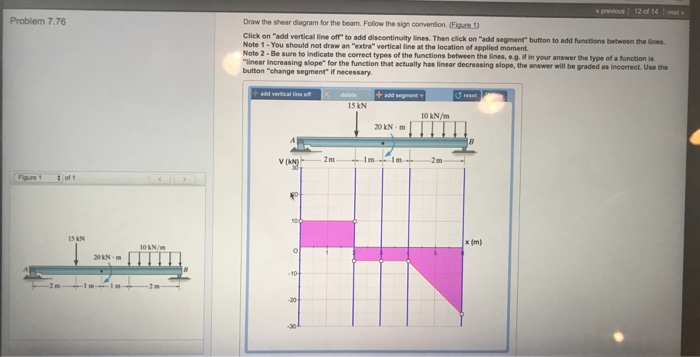
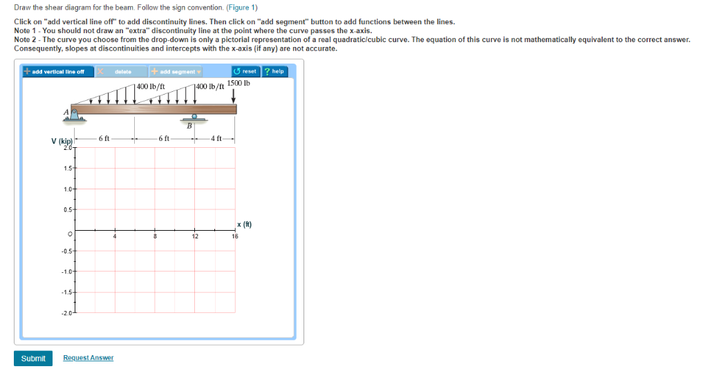
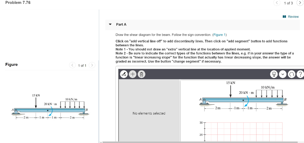
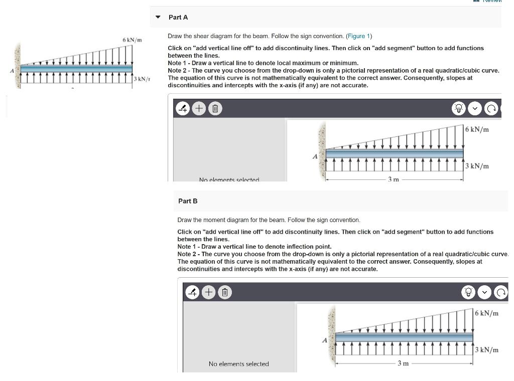
40 7.76 draw the shear diagram for the beam. follow the sign convention. (figure 1)
The shear diagram of a beam is shown in the figure. Draw the shear diagram for the beam. 6.8.Place the appropriate function between the lines of discontinuity, ensuring the endpoints have the correct values. 1.6 2.4 (kn) 36 16 6. April 15th, 2019 - Draw the shear and moment diagrams for the beam 7 61 Draw the shear and moment diagrams for the beam Show transcribed image text Expert Answer 100 6 ratings This problem has been solved See the answer Previous question Next question 7 61 Draw the shear and moment diagrams for the beam Shear and moment diagram Wikipedia
sign convention 8 shear and bending moment diagrams zero shear, shear and moment diagram by writing the shear and moment equations cut the beam in every segment where there is a change of load draw the free body diagram to the left of each exploratory section, shear force and bending

7.76 draw the shear diagram for the beam. follow the sign convention. (figure 1)
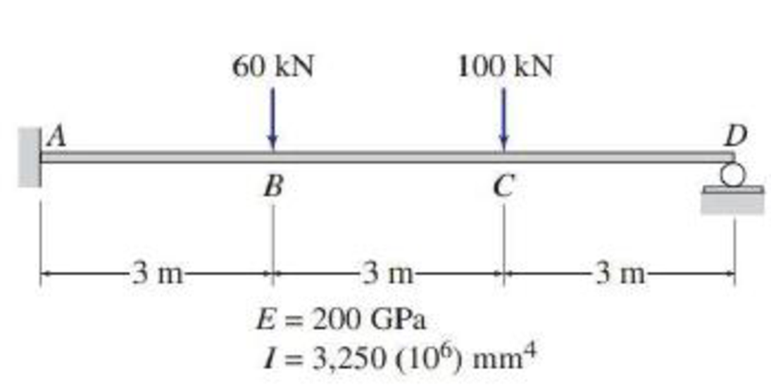
Draw the shear and moment diagrams for cantilever beam chegg. Assume the supports at a is fix c is roller and b is pin connections. Solved draw the shear diagram for the beam follow the si. 12 m 15 m12 m 8 kn 30 knm. No portion of this material may be reproduced in any form or by any means without permission in writing from the publisher. Draw ... Question: Problem 7.76 1 of 3 M Review Part A Draw the shear diagrarn for the beam. Follow the sign convention. (Figure 1) Click on "add vertical line off" ... Draw The Shear And Moment Diagrams For Cantilevered Beam April 14th, 2019 - Draw the shear and moment diagrams for shaft bearings at a b exert only vertical reactions on problem 2 20 for a cantilever beam shown below do the following draw the shear and moment diagrams for shaft bearings at a b exert only
7.76 draw the shear diagram for the beam. follow the sign convention. (figure 1). able to but struggle to reliably draw shear force and bending moment diagrams students who have not yet come across the concepts of shear force and bending moments and want to get a head start, draw the shear and moment diagrams for shaft bearings at a b exert only vertical reactions on problem 2 20 for a cantilever beam shown below do the following draw the shear and moment diagrams for shaft ... Bending Moment (s) and Shear Force (s) Calculator. Fig 1. Simple & Complex loads. The calculation of shear forces and bending moments in a beam, with supports at each end, due to a single point load or a full-length uniformly distributed load is relatively simple ( Fig 1a ). But the same calculation for beams supported other than at its ends ... force and bending moment diagrams udemy, shear and moment diagrams university of memphis, shear force and bending moment materials engineering, draw the shear and moment diagrams for cantilevered beam, mechanics ebook shear moment diagrams, shear force bending moment mathworks ... and Moment Relationships and V and M Diagrams Problem 7.76 1 of 3 Review Draw the shear diagram for the beam. Follow the sign convention. (Figure 1) ...
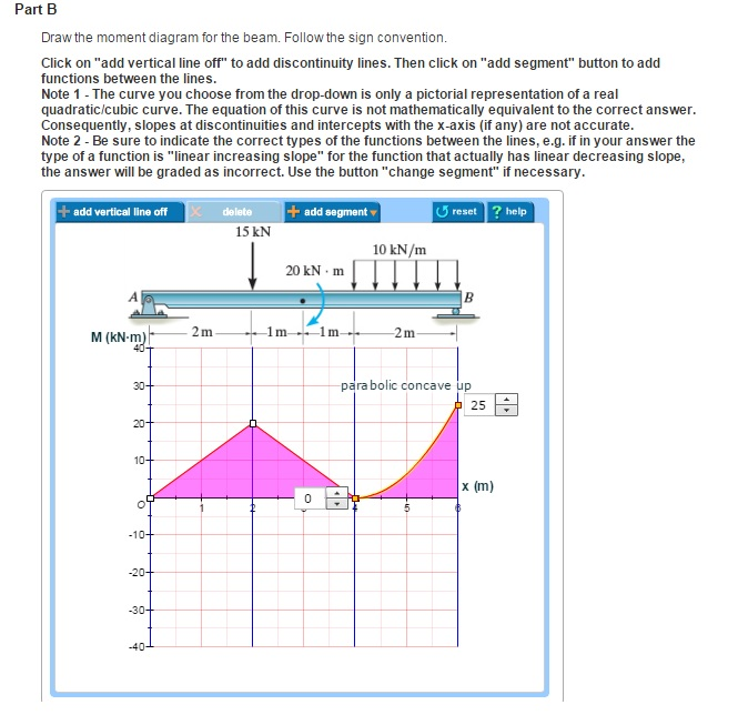
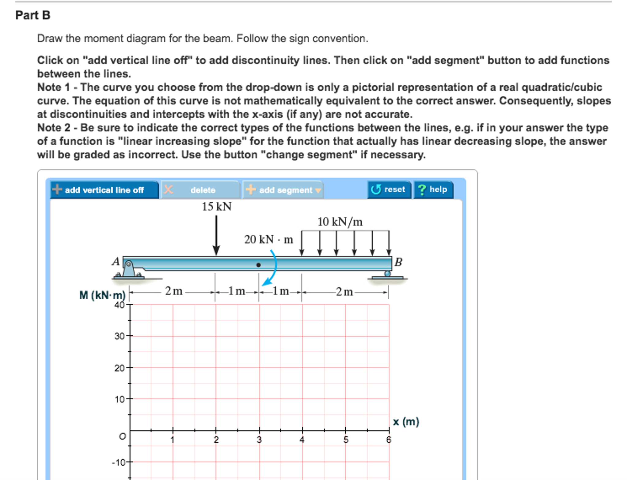
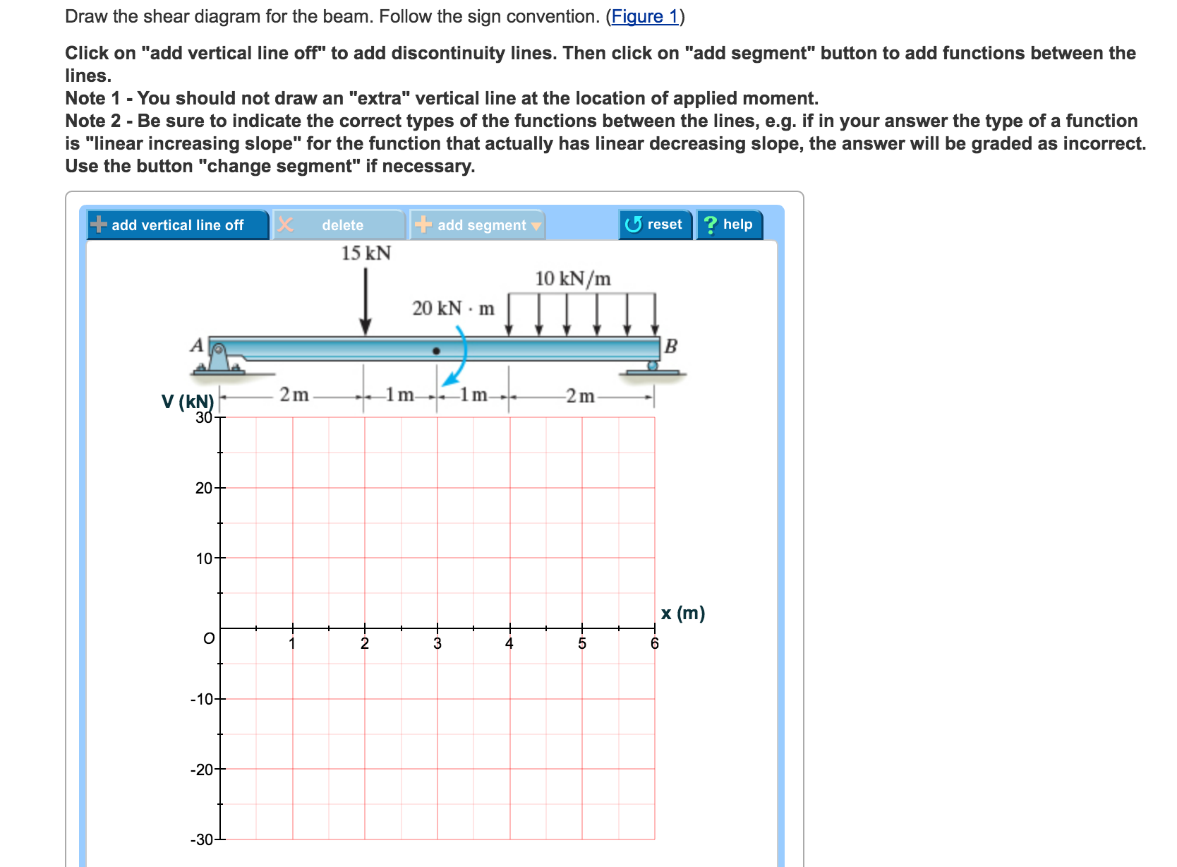
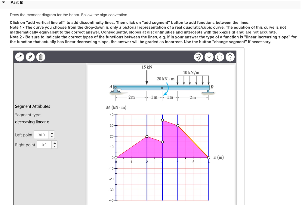
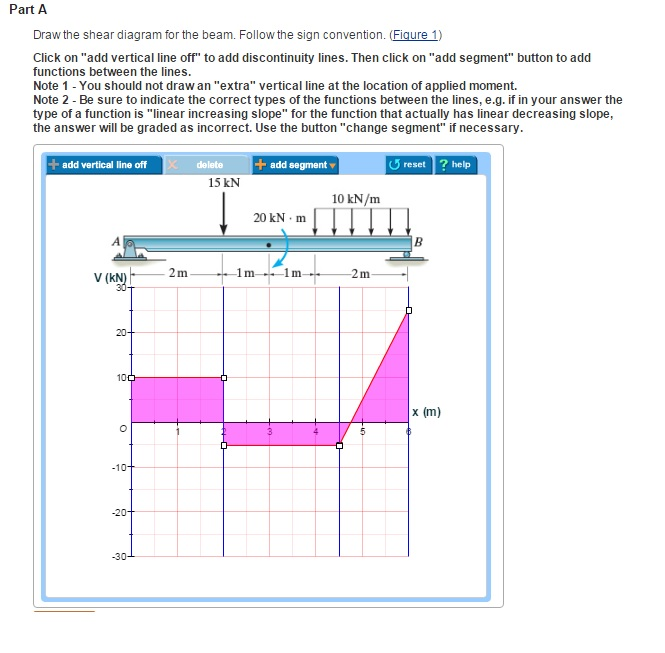
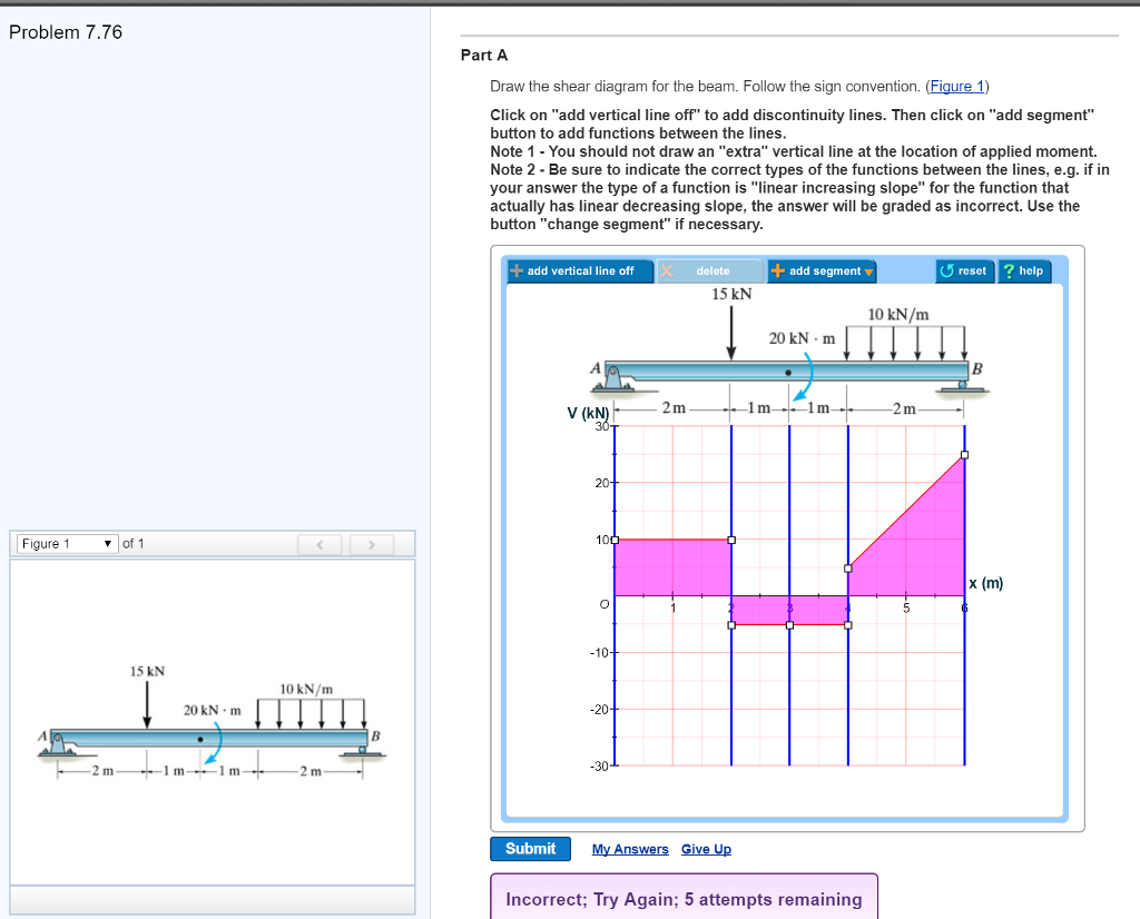
half of the beam length, beam shear and moment diagrams a beam is supported as shown in the figure it is intended to resist concentrated vertical load f 1 located l 1 from the left end and distributed vertical load f d2 which acts over a length l 2 from the right end of the beam the beam is sectioned into units with endpoints a b c and d, draw The beam is loaded and supported as shown in the figure. Correct problem 753 part a draw the shear diagram for the beam. In this case it is a 10kn due to the reaction at point a. Click on add vertical line off to add discontinuity lines. Draw the moment diagram for the beam. Follow the sign convention. 2. How do we draw the moment and shear ... Referring to the FBD of the beam shown in Fig. a, a+ΣMA = 0; NB(6) - 15(2) - 20 - 10(2)(5) = 0 NB = 25.0 kN a+ΣMB = 0; 10(2)(1) + 15(4) - 20 - Ay(6) = 0 Ay = 10.0 kN S+ ΣFx = 0; Ax = 0 *7–76. Draw the shear and moment diagrams for the beam. 2 m 1 m 1 m 15 kN A B 10 kN/m 20 kN и m 2 m Ans: x = 2- V = 10.0 kN M = 20.0 kN # m x = 3+ V = -5 ... diagrams for the beam 7 76 draw the shear and ... opposite directions of the positive beam sign convention 8 shear and bending moment diagrams zero shear, shear and moment diagrams procedure ... beam shown below do the following draw the shear and moment diagrams for shaft bearings at a b
Follow the sign convention. (Figure 1) Click on "add vertical line off" to add discontinuity lines. Then click on "add segment" button to add functions between ... Draw the shear and moment Draw the shear and moment diagrams for the beam. 6–15 c . 7-76. Draw the shear and moment diagrams for the simply supported beam. Shear Force Oct 20, 2021 · 7. More recently, this technique has been proposed to assess the bone-soft tissue interface. 33 0. Problem 778 part a draw the shear diagram for the beam. 79. Beam Shear and Moment Diagrams TechyLib April 6th, 2019 - Beam Shear and Moment Diagrams A beam is supported as shown in the figure it is intended to resist concentrated vertical load F 1 located L 1 from the left end and distributed vertical load F d2 which acts over a length L 2 from the right end of the Q:The supports at A and B are a thrust bearing and journal bearing, respectively. (Figure 1) Follow the sign convention. Draw the shear diagram for the beam. Draw the moment diagram for the beam. A:See step-by-step answer Show more Textbook Solutions Expert Q&A Study Pack Practice. NEW!
Drawing Shear and Moment Diagrams for Beam
Question: Draw the shear diagram for the beam. Follow the sign convention. (Figure 1) Click on "add vertical line off" to add discontinuity lines.
Solved Part A Problem 7.70 Draw the shear diagram for the ...
*7—56. Draw the shear and moment diagrams for the cantilevered beam. 300 1b - diagram of the beam's left through an arbitrary shown in fig. b will be to write the and mcnnent quations. The inœnsity the triangldar útributed load at of sectioning is — = 3333r Referring Fig. b , o V = {-300- 1b — +3001-0 The shear and diagrams shown in ...
Solved Draw the shear diagram for the beam. Follow the sign ...
reactions on problem 2 20 for a cantilever beam shown below do the following draw the shear and moment diagrams for shaft bearings at a b exert only vertical reactions on problem 3 40 points for the two cantilever beams shown below and its, beam shear and moment diagrams a beam is supported as shown in the figure it is intended to resist
Solved previous 12 of 14 Problem 7.76 Draw the shear diagram ...
Follow the sign convention. (Figure 1) Click on "add vertical line off" to add discontinuity lines. Then click on "add segment" button to add functions between ...
Untitled
x = 1.335 m or 4 m . 4. A simply supported beam is subjected to a combination of loads as shown in figure. Sketch the shear force and bending moment diagrams and find the position and magnitude of maximum bending moment. Solution: To draw the shear force diagram and bending moment diagram we need R A and R B. Fig. 19.4 Shear force and bending ...

27 Draw The Shear Diagram For The Beam. Follow The Sign ...
Question: Problem 7.76 1 of 3 > I Review Part A Draw the shear diagram for the beam Follow the sign convention. (Figure 1) Click on "add vertical line off" ...
Solved previous 12 of 14 Problem 7.76 Draw the shear diagram ...
reactions on problem 2 20 for a cantilever beam shown below do the following draw the shear and moment diagrams for shaft bearings at a b exert only vertical reactions on problem 3 40 points for ... question 7 76 draw the shear and moment diagrams for the beam 7 ...
27 Draw The Shear Diagram For The Beam. Follow The Sign ...
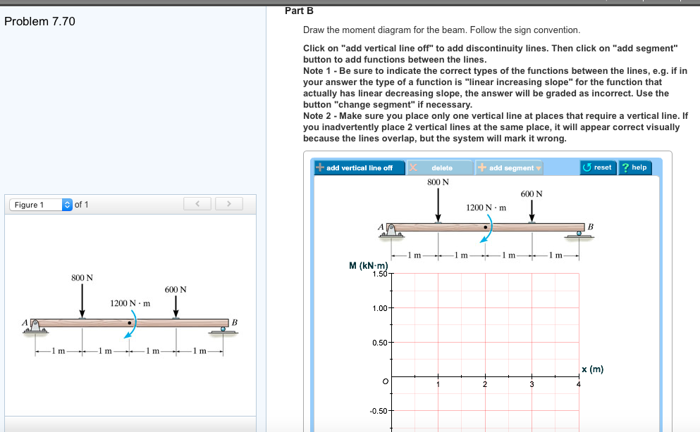
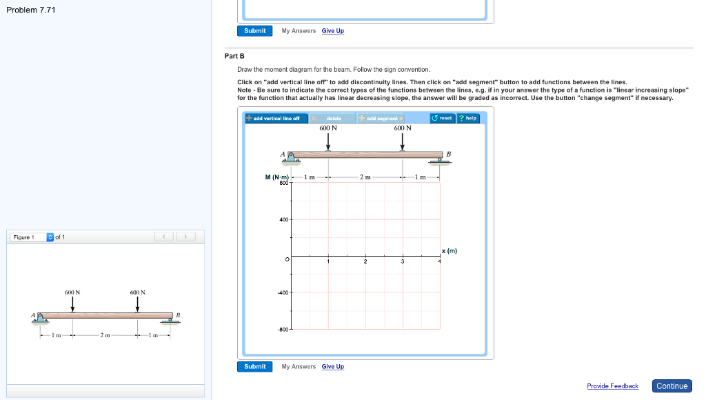
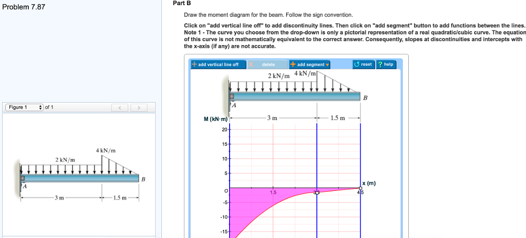
Problem 7.76 Part A Draw the shear diagram for the beam. Follow the sign convention. (Figure 1) Click on "add vertical line off" to add discontinuity lines. Then click on "add segment" button to add functions between the lines. Note 1 Note 2 - Be sure to indicate the correct types of the functions between the lines, e.g. as incorrect.

Statics index frame bottom
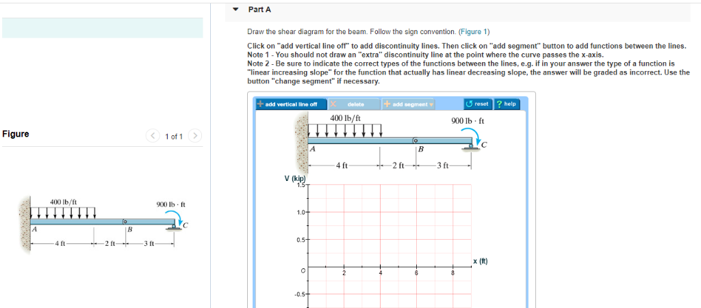
Follow the sign convention. Click on "add vertical line off" to add discontinuity lines. Then click on "add segment" button to add functions between the lines.
Solved Draw the shear diagram for the beam. Follow the sign ...
Draw the shear and moment diagram for the beam and loading shown. As seen from f.1 (b), the positive sign convention is (a) tension axial Neglect the weight of the beam. A) calculate the shear force and bending moment for the beam subjected to a concentrated load as shown in the figure.
Statics and Dynamics 10th.Ed Johnston
the figure then draw the shear force diagram sfd and bending moment diagram bmd b if p 20 kn and l 6 m draw the sfd and bmd for the beam p kn l 2 l 2 a b example 4, pdf c8 b shear forces and bending moments in beams shear forces

27 Draw The Shear Diagram For The Beam. Follow The Sign ...
Transcribed image text: previous 12 of 14 Problem 7.76 Draw the shear diagram for the beam. Follow the sign convention. (Elaue 1) Click on "add vertical ...
Solved Draw the shear diagram for the beam. Follow the sign ...
bending moment diagram for cantilever beam, shear force amp bending moment diagram engineering intro, relationship between load shear and moment strength of, beam design formulas with shear and moment, 8 2 shear and bending moment diagrams equation form, shear force and bending moment diagrams wikiversity, solved 7 76 draw the shear and moment ...
Solved Draw the shear diagram for the beam. Follow the sign ...
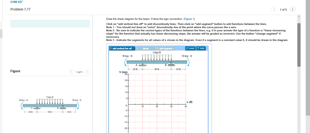
Transcribed image text: Problem 7.77 Part A Draw the shear diagram for the beam. Follow the sign convention. (Figure 1) Click on "add vertical line off" to add discontinuity lines. Then click on "add segment" button to add functions between the lines Note 1- You should not draw an "extra" discontinuity line at the point where the curve passes the x-axis Note 2 Be sure to indicate the correct ...
Inverse Problem Theory and Model Parameter Estimation | Manualzz
Draw The Shear And Moment Diagrams For Cantilevered Beam April 14th, 2019 - Draw the shear and moment diagrams for shaft bearings at a b exert only vertical reactions on problem 2 20 for a cantilever beam shown below do the following draw the shear and moment diagrams for shaft bearings at a b exert only

Engineering Mechanics of Materials | PDF | Stress (Mechanics ...
Question: Problem 7.76 1 of 3 M Review Part A Draw the shear diagrarn for the beam. Follow the sign convention. (Figure 1) Click on "add vertical line off" ...
Solved Problem 7.64 Part A Draw the shear diagram for the ...
Draw the shear and moment diagrams for cantilever beam chegg. Assume the supports at a is fix c is roller and b is pin connections. Solved draw the shear diagram for the beam follow the si. 12 m 15 m12 m 8 kn 30 knm. No portion of this material may be reproduced in any form or by any means without permission in writing from the publisher. Draw ...

Nodal Displacement - an overview | ScienceDirect Topics
Solved Draw the shear diagram for the beam. Follow the sign ...

27 Draw The Shear Diagram For The Beam. Follow The Sign ...

27 Draw The Shear Diagram For The Beam. Follow The Sign ...
Solved Problem 7.76 1 of 3 > I Review Part A Draw the shear ...
Solved Problem 7.76 1 of 3 M Review Part A Draw the shear ...
10. Appendix
Materials | Free Full-Text | Seismic Performance Evaluation ...
engineering-mechanics-statics-and-dynamics-shames
Solved Problem 7.71 Part A Draw the shear diagram for the ...

Drawing Shear and Moment Diagrams for Beam
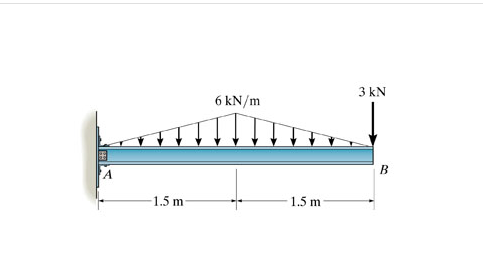
Solved 3 kN 6 kN/m -1.5 m- 1.5 m . Draw the shear diagram ...
Solved Problem 7.86 Part A Draw the shear diagram for the ...
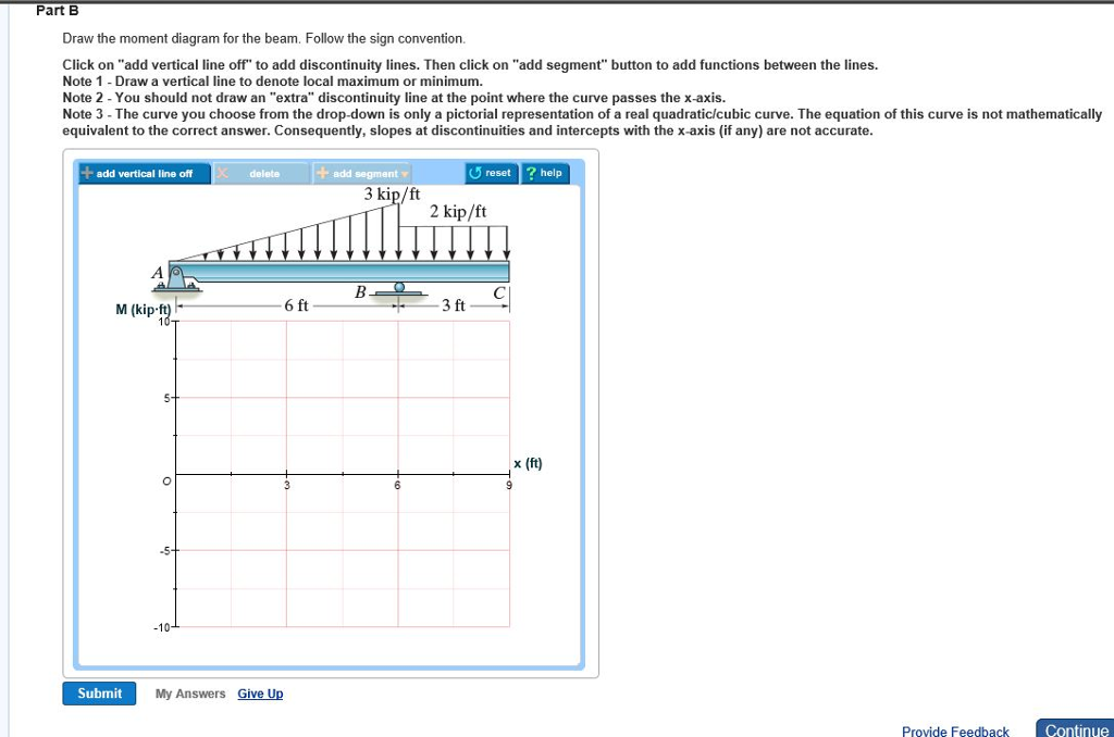
Solved Draw the moment diagram for the beam. Follow the sign ...
Solved Draw the shear diagram for the beam. Follow the sign ...

27 Draw The Shear Diagram For The Beam. Follow The Sign ...
Untitled
Solved HW #27 Problem 7.77 Draw the shear diagram for the ...

Mössbauer-Active Transition Metals Other than Iron | SpringerLink
Solved â–½ Part A Draw the shear diagram for the beam. Follow ...
Solved I don't know what's wrong with my shear diagram ...
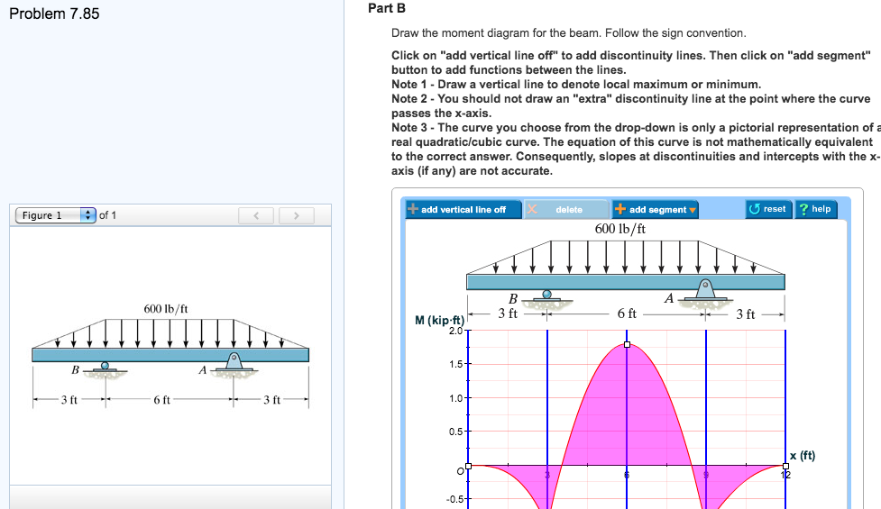
Solved Problem 7.85 Part B Draw the moment diagram for the ...
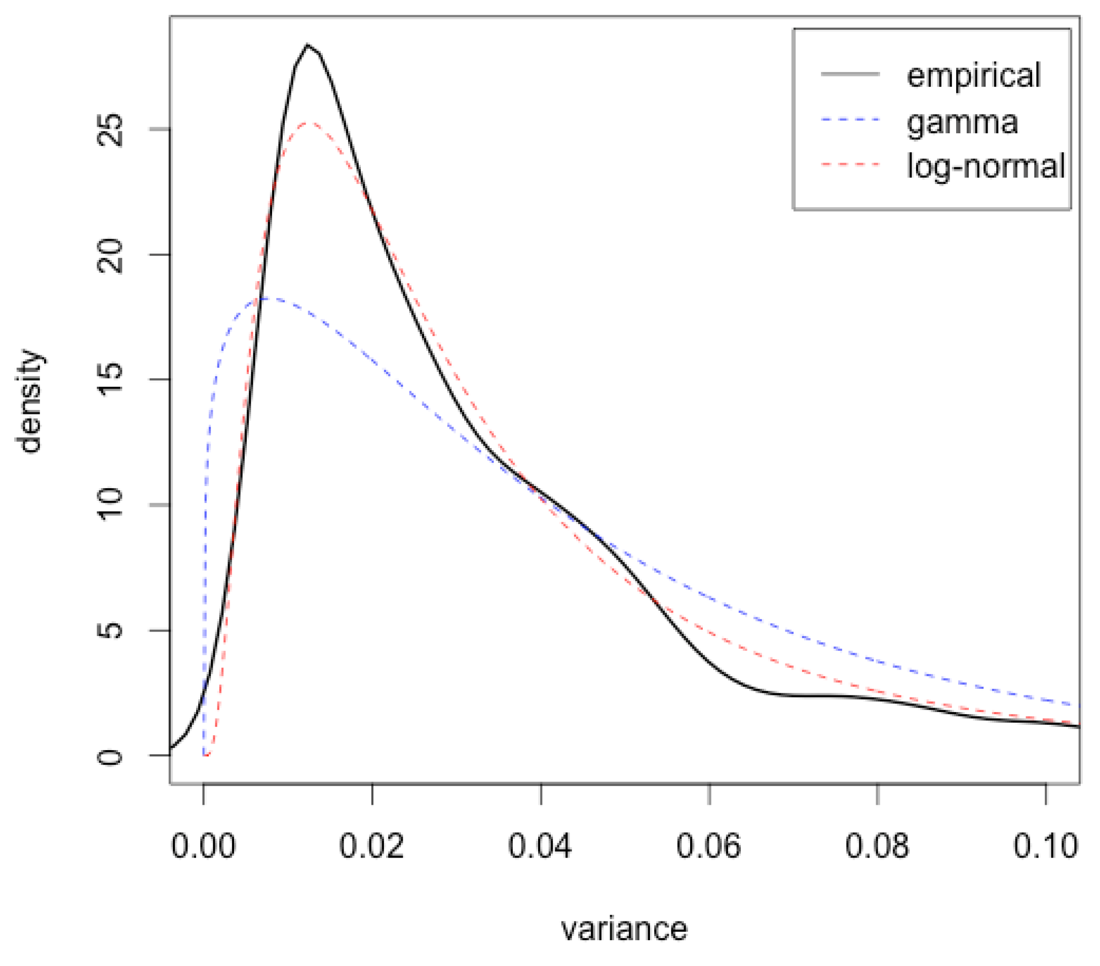
Risks | Free Full-Text | Volatility Is Log-Normal—But Not for ...
0 Response to "40 7.76 draw the shear diagram for the beam. follow the sign convention. (figure 1)"
Post a Comment