40 hurst line lock wiring diagram
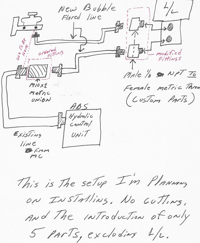
1/4" Lock Washer (2) 1/4-20 Nut (2) Female Terminal (4) Lit Momentary Switch ... front brake line from screwing into the Hurst brake line. Unscrewing Master Cylinder rear brake line might be required to move flex line. ... (See wiring diagrams for wiring details on page 10) and ... I've been looking at the Hurst roll control/line lock kits on Summit and eBay, then looked at the Hurst plumbing diagram and have a problem with it.....someone on another thread said something about a car not passing tech IF you went from the master cylinder to the roll control/line lock solenoid, then to a proportioning valve which splits to the right front and left front brake lines.
wrench is recommended on all line fittings while in- ... trol on vehicles equipped with anti-lock or split ... instructions before installing your HURST.7 pages

Hurst line lock wiring diagram
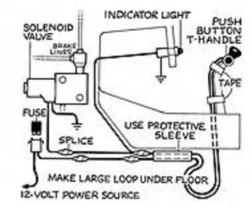
6. Join the red wire from the lamp, one of the wires from the switch (either will work) and the remaining black wire of the solenoid valve. 7. Using a length of 18-gauge wire, splice one end to the remaining wire of the switch and connect the other end to a switched positive terminal so that the brake lock is only operable with the ignition ... In this first part of the line lock installation, we will get the solenoid mounted and new brake lines plumbed.Products Used:Hurst Roll Control - https://amz... Wiring: All wiring connections should be soldered and covered with shrink sleeving. 1. Disconnect battery. 2. Wire per diagram on next page. 3. Reconnect battery and test for correct operation. Operation: TO ACTIVATE: Depress brake pedal and hold, depress control switch and hold, release brake pedal. Brakes are now locked.
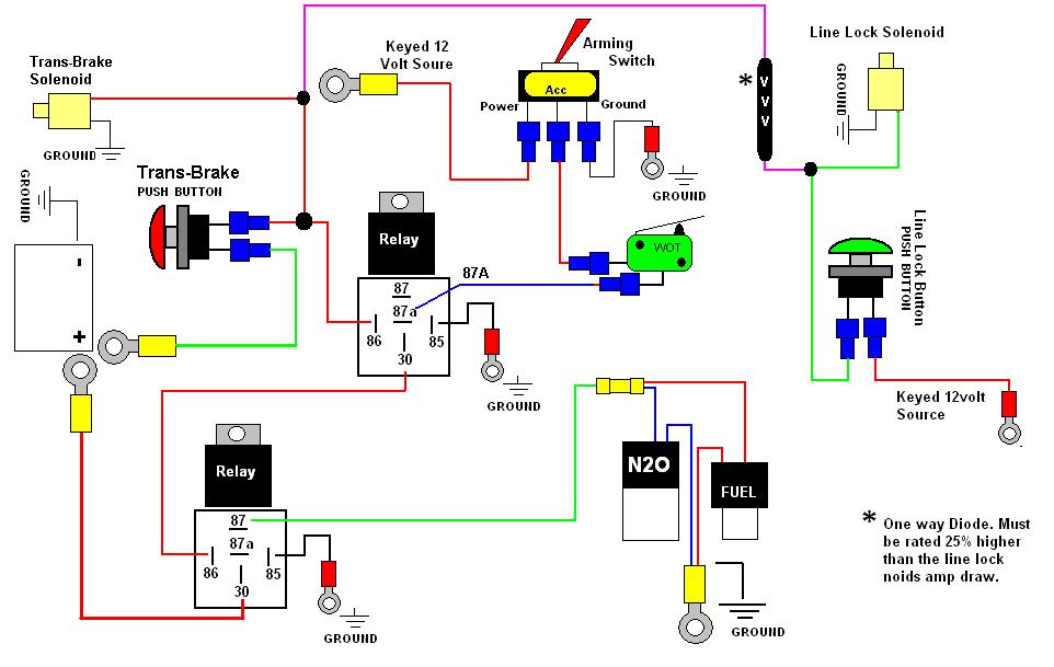
Hurst line lock wiring diagram. Here I show you how I installed the line lock in my g-body. [UNBOXING VIDEO] I also show you my favorite and what I think is the best AN JIC fitting flaring ... I think I have the basic wiring nailed down, just need some help with the indicator lights. Here's what I want for functionality: 1. I want to activate the Line Lock, Transbrake and 2-Step off my Shifter Handle Button. 2. I want the 2-Step and Transbrake to be wired together on one toggle switch and the Line Lock on another toggle switch. 3. I received a wiring diagram from O1mrquick (Thanks). I just haven't found a source for the connectors yet. I wanted to wire the reverse lockout to a shifter mounted switch (think Hurst line lock T handle), the speedomter to my Autometer electric speedometer and the backup lights to, well, my backup lights. Stereo & Electronics - Need SLP Line Lock Wiring Diagram - Somehow lost the instructions when messing around with my car and now need. Disconnect negative (-) battery terminal. If more wire is needed than what is provided, use #18 gauge standard insulated automotive wire to assure good.
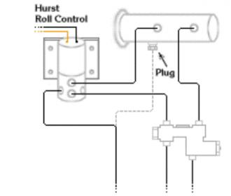
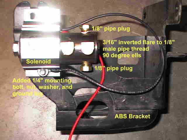
wiring. DIAGRAM 2 Instr Line Lock SUM-760000 10/22/09 3:08 PM Page 3. 4 FORM INST760000 10/09 Made in USA Printed in USA Summit Racing Equipment 1200 Southeast Avenue Tallmadge, Ohio 44278 www.SummitRacing.com Technical: 1-330-630-0240, Monday through Friday 9 am to 9 pm ET After installation of brake lines and fittings is complete, connect electric wiring of solenoid according to instructions and diagrams included with the Hurst ...2 pages The Hurst® Roll/Control® is used primarily in drag racing to provide positive locking action to the front wheels of race cars, reducing the chance of "Rolling the Lights" and producing more effective "Burn Outs" for heating up the tires. Rigorous testing has proved a 1/100,000 of a second release time and vibration tests have seen up to 30 G's applied without mechanical failure. Adaptable to ... Line Lock Wiring This site is best viewed in 1024x768 resolution. Disclaimer: Below is a picture of my Hurst Line Lock and a diagram of how I wired it. I disliked the large red bulb supplied with the Hurst kit so I wired it to light the factory BRAKE idiot light in the dash instrument cluster. I tapped the power at the parking brake switch and ...
Your Hurst Universal Roll Control Line Lock Kit features three outlet ports and is covered by a 90-day warranty; Description: Cruise down the highway with the confidence of a drag racer thanks to a new Hurst Universal Roll Control Line Lock. Used in drag racing to effectively lock the front wheels, these top-notch lock kits are exactly what you ... 1. Install the supplied female crimp terminals to two suitable lengths of wire using at least 16 gauge wire. 2. Plug each female connector onto the spade terminals of the micro switch located in the plastic switch housing. 3. Using the wiring diagram below as a guideline, install the switch wires into your starting circuit. 4. Hurst Roll Control Set Up and Install Part 1 1. Hurst's Roll Control (or "Line Lock") is a pretty simple device. Once engaged by way of a switch, the solenoid maintains brake fluid pressure at the front wheels on your car. The back brakes have no pressure, allowing you perform an effortless burnout. Back to Post. This switch kit can be used with any system (Line Lock, Nitrous, Transbrake) to provide an ... (See wiring diagrams for wiring details) and should be ... A highly trained technical service department is maintained by Hurst Performance to answer your
Line Lock.....help!!
(See wiring diagram on page 7) WIRING INSTALLATION STEP 10. Pass wiring through existing access points ( one is located on the driver's side firewall). Avoid allowing wires to chafe by using the existing or a new grommet. 12V source NOTE: The Hurst Roll Control Solenoid Valve is designed for 12V DC operation only. For added safety,

Line Lock Wire Diagram - Wiring Diagram
This Line Lock has multiple ways to lock the brakes on your vehicle. It allows you to lock the front brakes only, the rear brakes only, or lock all four corners. Another nice feature is you can add a brake light pressure switch right into the housing of the valve to simplify wiring in brake lights.

Install a Brake Line-Lock - How To - Hot Rod Network
Put simply, Line-Lock is a solenoid that you activate from inside your car. A solenoid is a simple device made up of only a few pieces: a coil of tightly wound copper wire, a housing, and a plunger made of magnetic material. When electrical current is applied to the coil, a magnetic field forms, which draws the plunger in and converts the ...

Mustang Hurst Line Lock (1975-2014) Installation Instructions
This white molded shift knob is ideal for use with Line lock systems, trans brake, nitrous oxide systems or other 12 volt accessories. *FOR USE ONLY WITH THE HURST 2010-2014 Camaro V8/V6 Manual Billet Shifter Kit OR compatible shifter using 5/16-18 in., 3/8-16 in, 3/8-24 in., 1/2-20 in. threaded shifter stick!*

26 Hurst Line Lock Wiring Diagram - Diagram Wiring Site
Car Stereo Kenwood Wiring Diagram : 3 / Exterior Car Door Parts Diagram : Baggage Room Tri... Circuit Electrical Interlocking Wiring Diagram - F... Hurst Line Lock Wiring Diagram / Line Lock Install... Heat Pump Wiring Diagram Schematic / How To Instal... International 9400I Wiring Diagram / S082252 Pdf P...

Mustang Hurst Line Lock Installation Kit (1965-2014 ...
wow , ive had same hurst line lock since 1983, this is the third car it has been in and i got it USED . did not know you needed to rebuild them every few years. think ill leave it alone . Save Share. Reply. 1 - 20 of 27 Posts. 1; 2; Next. 1 of 2 Go to page. Go. Join the discussion. Continue with Facebook.

Hurst Line Lock Wiring Diagram - General Wiring Diagram
of brake systems. Diagrams of these system are shown on pages 2 and 3. Check your brake system and locate the comparable system on the diagrams to install your HURST Roll/ControI. Electrical installa- tion is the same on all vehicles—See instructions and diagram on paåe 4. Congratulations on the purchase of your HURST

33 Line Lock Wiring Diagram - Wiring Diagram List
1/4" Lock Washer (2) ... 13mm wrench on brake line nut Clean Rag STEP 7. Install Hurst Roll Control mounting bracket. Add a few drops of loctite (red) to bolt threads.Place first ... (See wiring diagram for wiring details) and should be incorporated into the wiring circuit. The fuse can protect the electrical system in

LineLock/Transbrake/2-Step Wiring Help Needed ...
- Ground line lock unit at closest chaisis spot. - Ran a single wire inside the car through gromet by brake cylinder. This is for powering the line lock. - Inside the car I used the cig lighter for power. Used a simple splice/tap connector to tap the wire with out having to cut it. - The switch goes in the power line with a fuse.

Hurst Line Lock Wiring Diagram - Diagram Resource Gallery
Hurst "Roll Control" (line lock) wiring? Today a young friend of mine installed my Hurst line lock, but I think there is something wrong with wiring. I'm electrically challenged, but the way I read the instructions the momentary switch light is supposed to come on when you turn on the rocker switch.
Hurst Line Lock Wiring Diagram - General Wiring Diagram
Once line is. Below is a picture of my Hurst Line Lock and a diagram of how I wired it. I disliked the large red bulb supplied with the Hurst kit so I wired it to light the factory BRAKE idiot light in the dash instrument cluster. Wiring: All wiring connections should be soldered and covered with shrink sleeving. 1.
![[DIAGRAM] Meyer Pistol Grip Wiring Diagram FULL Version HD ...](https://az417944.vo.msecnd.net/diagrams/manufacturer/snapper-pro/snapper-pro/walk-behind-mowers/pro-express-series/7082434-spe151kw-15hp-kawasaki-series-1/electrical-components-pistol-grip-handle/diagram.gif)
[DIAGRAM] Meyer Pistol Grip Wiring Diagram FULL Version HD ...
2. Find a location to place the Hurst Line Lock Solenoid from the Hurst Line Lock Kit. An easy location is by the master cylinder and distribution block. 3. Use a drill and the 7/32-inch drill bit to drill three holes in the metal. 4. Fasten the solenoid to the Mustang engine bay using the supplied 10mm bolts. 5.
Exploring Chelsea Market in New York
Wiring: All wiring connections should be soldered and covered with shrink sleeving. 1. Disconnect battery. 2. Wire per diagram on next page. 3. Reconnect battery and test for correct operation. Operation: TO ACTIVATE: Depress brake pedal and hold, depress control switch and hold, release brake pedal. Brakes are now locked.

34 Hurst Line Lock Wiring Diagram - Wiring Diagram Database
In this first part of the line lock installation, we will get the solenoid mounted and new brake lines plumbed.Products Used:Hurst Roll Control - https://amz...
Hurst pistol grip line lock wiring | NastyZ28.com
6. Join the red wire from the lamp, one of the wires from the switch (either will work) and the remaining black wire of the solenoid valve. 7. Using a length of 18-gauge wire, splice one end to the remaining wire of the switch and connect the other end to a switched positive terminal so that the brake lock is only operable with the ignition ...
Hurst Line Lock Wiring Diagram - Derslatnaback

Girl in High Line

26 Hurst Line Lock Wiring Diagram - Diagram Wiring Site

30 Hurst Line Lock Wiring Diagram - Wiring Diagram List
Line Lock Wire Diagram - Wiring Diagram
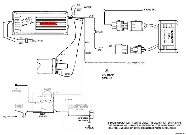
Pro-Flo and MSD 6AL2 w/Clutch and Line Lock Rev Limiter ...

92016HS SJM 6th Gen 2016-2018 Camaro Hurst-Style Line Lock Kit
New York Street Art

Mustang Hurst Line Lock Installation Kit (1965-2014 ...

Diagram PIC Photo by smws6ta | Photobucket
Line Lock Wire Diagram - Wiring Diagram
Hurst Line Lock Wiring Diagram
Paging Nx Ricky - LS1TECH - Camaro and Firebird Forum ...
![New Page 1 [maliburacing.com]](http://www.maliburacing.com/linelock/linelock_fig1.gif)
New Page 1 [maliburacing.com]
roger vivi ersaks: 2008 Colorado Wiring Diagram

The view from the high line in Manhattan NYC.

Hurst Line Lock Wiring Diagram - Wiring Schema

34 Line Lock Wiring Diagram - Wire Diagram Source Information
Hurst Roll Control Install - MustangForums.com

NovaResource - Line Lock Wiring

Sitting in LA
Hurst Roll Control Line Lock Instructions

Hurst Line Lock Wiring Diagram - Wiring Diagram
Sjm Hurst style line lock system - Camaro5 Chevy Camaro ...

Hurst Line Lock Wiring Diagram
0 Response to "40 hurst line lock wiring diagram"
Post a Comment