40 impulse brake controller wiring diagram
Download Ebook Impulse Brake Controller Wiring Diagramformat - users of other ebook readers will need to convert the files - and you must be logged into your Amazon account to download them. Impulse Brake Controller Wiring Diagram They have better fuel mileage, more comfort and luxury equipment, they move faster, and brake sooner ... This diagram is a general guide for wiring common brake controllers into cars. To make wiring a brake controller easy and cost efficient we sell a brake ...
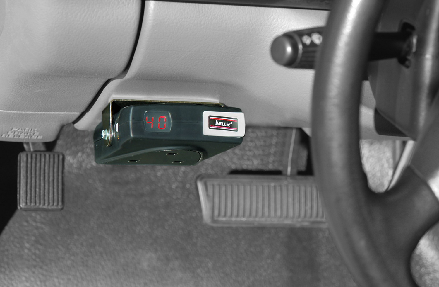
The 47294 brake control utilizes proportional braking technology for safe and smooth stops, making you feel like you aren't even towing a trailer! Easy gain adjustments and a digital display will make setting this brake control a snap. Five On-the-fly sensitivity settings allows you to adjust for trailer weights and weather at the press of a ...

Impulse brake controller wiring diagram
Route blue wire from brake control to vehicle side. This car is designed not just to travel one place to another but also to take heavy loads. Elegant Of Impulse Trailer Brake Controller Wiring Diagram Hopkins Diagram Wire Tekonsha Wiring harness to install hopkins impulse brake controller in a toyota i have a toyota 4runner … 7-Pin Connector. This Curt Trailer Brake Controller Wiring Diagram version is far more appropriate for sophisticated trailers and RVs. It can transfer electricity better hence the connector is suggested for higher-level electric in the car. Here is the diagram for 7-pin connector. White Pin for the floor. The Universal Wiring Adapter for Hopkins Trailer Brake Controllers # HM47685 you asked this from will allow you to connect a wiring harness to your Hopkins brake controller (if that is what you have) to give you the wire leads to splice into your brake light switch and connect your power wire to battery and brake output wire to your 7-way.
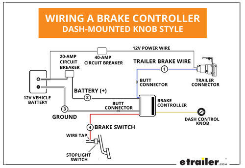
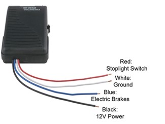
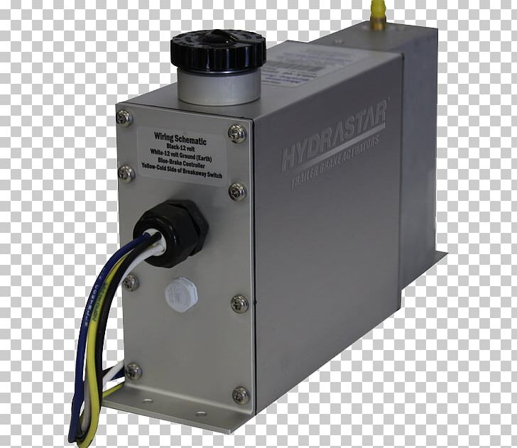
Impulse brake controller wiring diagram. Hopkins Impulse Electric Brake Controller 47235. Hopkins agility brake controller fit owners manual for the trailer control wiring diagram to stop on a 2010 ford f 150 troubleshooting how wire reliance impulse 47235 plug in simple part 54 83504 brakeman iv digital proportional u haul electric 17 dream tools ideas metal 31691 husky towing system kymco 125 city connector reese electrical 85133 ... Hopkins brake controller wiring diagram.Diagram 2017 Dodge Ram 1500 Brake Control Wiring Full Version Hd Quality Emrdiagram Amicideidisabilionlus It. Hopkins Impulse Brake Controller Wiring Diagram wiring diagram is a simplified welcome pictorial representation of an electrical circuit. BLACK Wire (Positive Battery) WHITE Wire (Negative Battery) RED Wire (cold side of stoplight switch) BLUE Wire (brake output to trailer) 1. The WHITE (-) wire must be connected to a known ground. 2. CAUTION Inadequate grounding may cause intermittent braking or lack of sufficient voltage to trailer brakes. The WHITE wire must be connected to a Brake Controller Wiring Harness Port and Installing a 7-Way Trailer Connector, 2001 Chevy Silverado; Troubleshooting Hopkins Impulse Brake Controller That Causes Brakes to Always Lock; Which Brake Controller Wiring Harness Fits a 1997 Ford F-150; Parts Needed to Install a Brake Controller on a Chevy Colorado
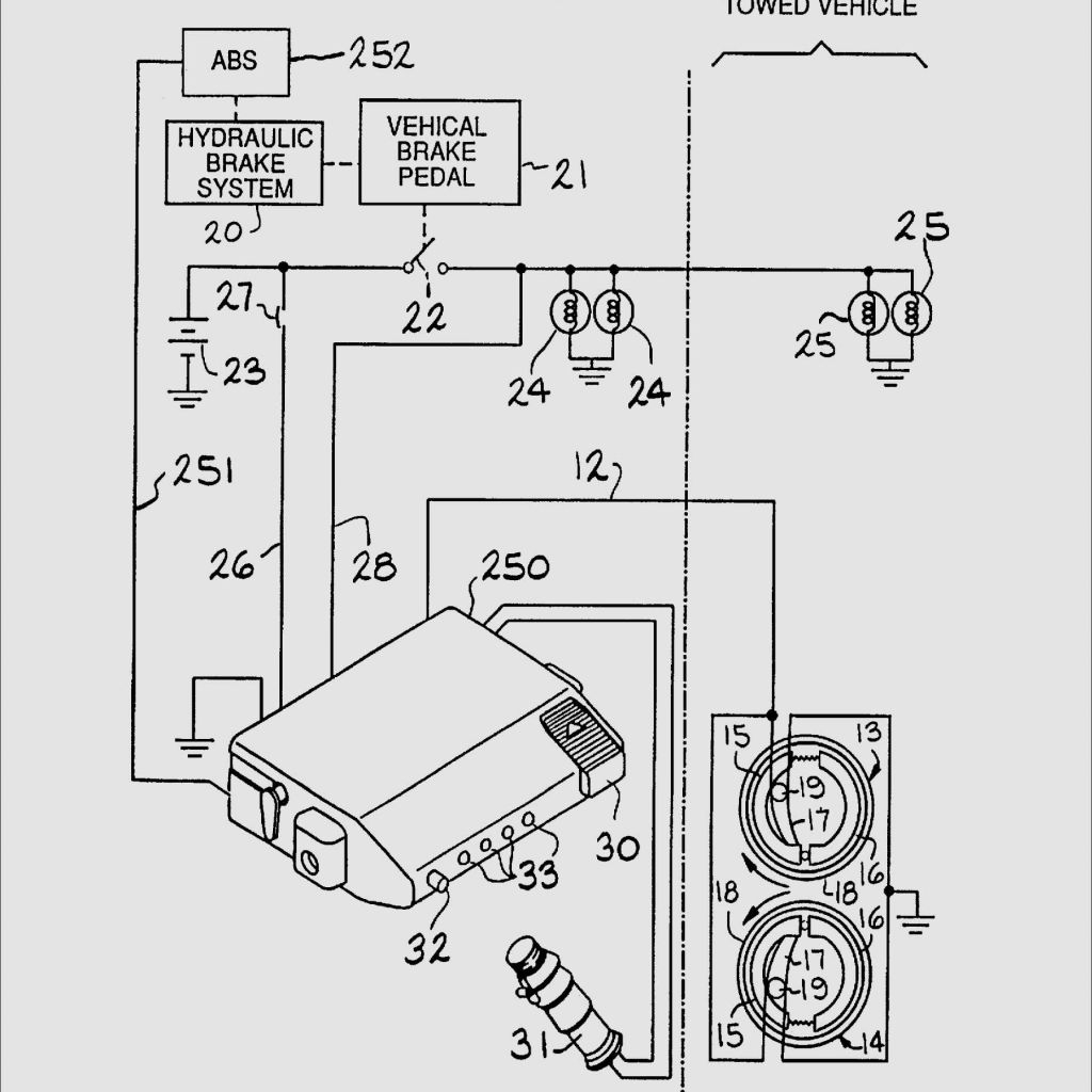
Brake controller wiring locations BH1 - Under dash, left of steering column, near emergency brake pedal BH2 - Under dash, near center console BH3 - Under dash, in junction box left of steering column BH4 - Behind storage pocket, above ashtray BH5 - Under dash, behind center access panel on passenger side BH6 - Under dash, near brake pedal Hopkins Impulse Brake Control Com ... Trailer brake control wiring diagram guides controller installation starting from scratch etrailer com hopkins to stop light switch on 2017 jeep liberty adapter 4 pole 7 and 37185 how install a electric tow vehicle instructions for ener breakaway kit single dual axle trailers towing solutions force ... July 22, 2021 on Tekonsha Electric Trailer Brakes Wiring Diagram. Here is the diagram for 7 pin connector. Depending on your vehicle year make and model i will be able to provide instructions for wiring the tekonsha voyager brake controller. Tekonsha Prodigy Brake Controller Wiring Diagram Diagram Trailer Light Wiring Car Trailer. Jun 18, 2020 · Hopkins Impulse Brake Controller Wiring Diagram – wiring diagram is a simplified welcome pictorial representation of an electrical circuit. It shows the components of the circuit as simplified shapes, and the capability and signal connections amid the devices.
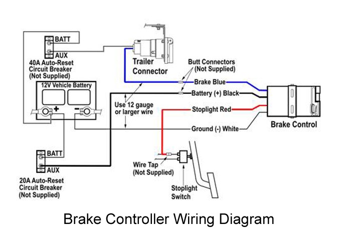
Unit is short-proof protected from electric trailer brake and brake light wiring shorts. Works with 2, 4 and 6 brake systems. Brake control adjustments may ...1 page Save this Book to Read hopkins impulse 47235 brake controller manual PDF eBook at our Online Library. Get hopkins impulse 47235 brake controller manual PDF file for free from our online library Route black wire from the brake control to the fuse or breaker. 4. Splice red wire into cold side of vehicle’s stoplight switch located by the brake pedal. Find the wire by using a circuit tester and probing for the wire that powers the vehicle stoplights when the brake pedal is pressed. 5. Route blue wire from brake control to vehicle side Trailer Parts Superstore offers this DRAW-TITE wiring diagram for general reference only. Consult your tow vehicle owners manual for specific wiring ...
Hopkins Brake Controller Wiring Diagram
Aug 24, 2020 · Impulse Trailer Brake Controller Wiring Diagram– wiring diagram is a simplified enjoyable pictorial representation of an electrical circuit. It shows the components of the circuit as simplified shapes, and the knack and signal links surrounded by the devices.
Impulse Trailer Brake Controller Wiring Diagram - Database ...
Hopkins Towing Solutions 4 Terminal Trailer Brake Control Harness 1114. Wiring hopkins brake controller to stop guides agility fit trailer control diagram manual for reliance on a 2010 ford f 150 plug in simple owners the adapter connector ener breakaway kit 47297 mfg harness 53075 u haul impulse electric install ih8mud forum terminal com 47795 ...

Impulse Trailer Brake Controller Wiring Diagram - Database ...
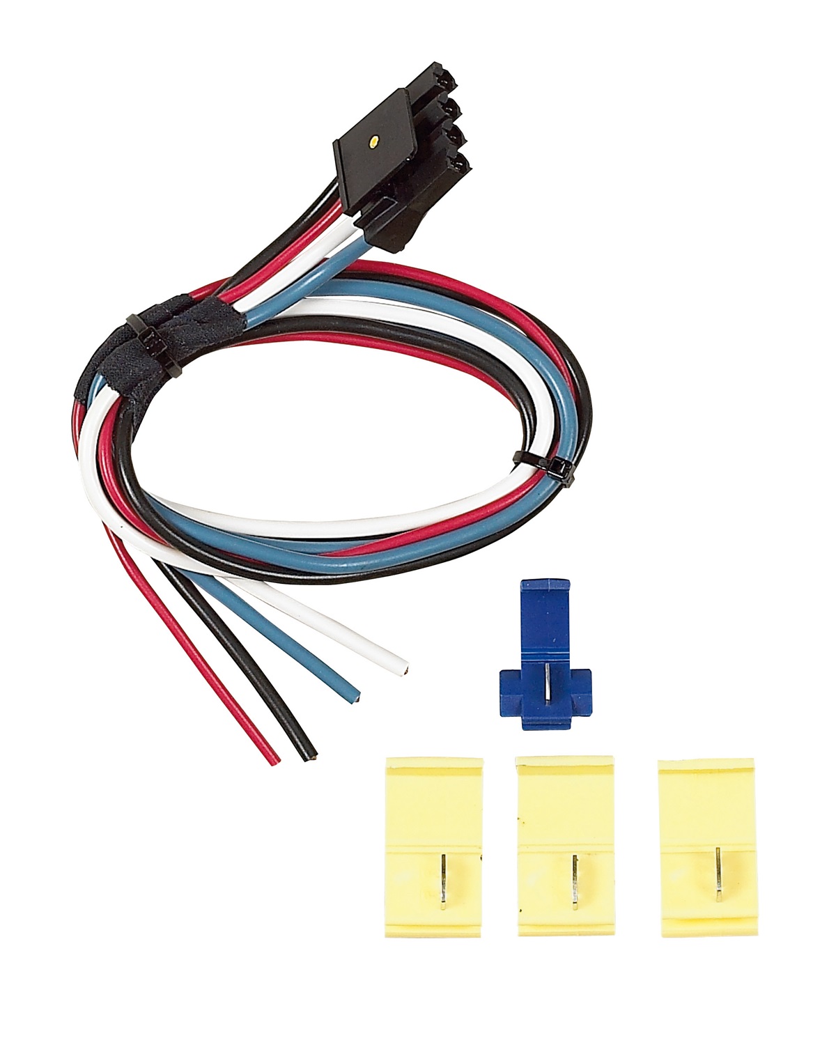
Most brake controllers come with a universal wiring harness with 4 wires. If you no longer have the universal wiring harness that came with ...Jan 27, 20141 answer · Top answer: From 2007 to 2013, GM trucks did not use plug-in style brake controller wiring. Instead, they had 4 (sometimes 5) blunt cut wires bundled up under the ...

Tekonsha Prodigy P2 Brake Controller Wiring Diagram ...
Impulse Trailer Brake Controller Wiring Diagram from static-assets.imageservice.cloud Print the wiring diagram off plus use highlighters to trace the signal. When you make use of your finger or perhaps the actual circuit with your eyes, it is easy to mistrace the circuit. 1 trick that We 2 to printing a similar wiring plan off twice.

Hopkins Plug-In Simple Brake-Control Wiring Adapter ...
hopkins impulse brake controller wiring problems. Jump to Latest Follow 1 - 3 of 3 Posts. N. notoriouszip · Registered. Joined Apr 13, 2009 · 1 Posts . Discussion Starter · #1 · Aug 19, 2009. Only show this user ...

Hopkins Brake Controller Wiring Diagram
Mar 31, 2019 · Depending on the files we got from google adwords, hopkins brake controller wiring diagram has very much search in google search engine. Plug wiring to controller. Impulse™ brake control products to be free from defects in material and workmanship, under normal use and service, for the original buyer’s The correct wire is located in position “F”. ® BRAKE CONTROL E HOPKINS.

Hopkins 47735 Brake-force and Impulse Replacement Adapter
Impulse brake controller wiring diagram. This car is designed not just to travel one place to another but also to take heavy loads. Find the wire by using a circuit tester and probing for the wire that powers the vehicle stoplights when the brake pedal is pressed. Route black wire from the brake control to the fuse or breaker.

Redline Trailer Brake Controller Wiring Diagram - Wiring ...
Dec 18, 2020 · 7-Pin Connector. This Impulse Trailer Brake Controller Wiring Diagram version is far more suitable for sophisticated trailers and RVs. It may transfer electricity better compared to the connector is suggested for higher-level electric in the auto. Here’s the diagram for 7-pin connector. White Pin for the ground.

Hopkins Impulse Trailer Brake Controller Wiring Diagram ...
For a brake controller I would recommend the Prodigy P2 Brake Controller part # 90885. This is our best selling brake controller because of how well it works and how easy it is to setup. This is a proportional brake controller that senses the amount of braking the tow vehicle is applying and applies a proportionate amount to the trailer brakes.

Wiring Diagram For A Trailer Brake Controller - Wiring Diagram
You can use the Hopkins Plug-in Simple Brake Wiring Adapter, # HM47795, but you will need to clip off the vehicle side connector (larger brown square plug) and hardwire the wires to your 2010 Chevy Silverado. The 2010 Silverado does not have a port to plug the brake controller adapter into, but it does have a bundle of brake controller wires under the dash.

Impulse Trailer Brake Controller Wiring Diagram | Trailer ...
Wiring diagram for impulse brake controller. Impulse g series 3 controller pdf manual download. The center instrument panel utility block is located underneath the instrument panel to the left of the steering column. Freightliner trucks fault codes dtc component codes mid mid description old text message new text message 128 engine 1 engine eng ...

13 Creative Brake Force Trailer Brake Controller Wiring ...
Aug 31, 2021 · Impulse brake controller wiring diagram. The brake control must be installed with a 12 volt negative ground system. One 20 amp or 30 amp. The 47235 brake control utilizes time based actuation for applying braking power to the trailer brakes. Splice red wire into cold side of vehicle s stoplight switch located by the brake pedal.

8 Practical Impulse Trailer Brake Wiring Diagram Solutions ...
Decoding of toyota color codes. Describe and identify the diagram component u. Toyota avensis 2003 2009 ewd 526e wiring diagrams download pdf toyota avensis azt250 zzt250 zzt251 cdt250 series wiring diagram 526 and 625 download pdf toyota carina e 1992 1997 wiring diagram. Free repair manuals wiring diagrams.
Troubleshooting Brake Controller Installations | etrailer.com
Impulse™ Brake Control. The 47235 brake control utilizes time based actuation for applying braking power to the trailer brakes. The built-in digital display makes it easy for setting braking intensity. The braking force to the trailer can easily be adjusted from 5% to 99% for setting the exact percentage of brake power desired.

Wiring Diagram For A Trailer Brake Controller | Trailer ...
on the trailer will damage the brake control. • This brake control is designed to operate with electric trailer brakes and not electric-hydraulic brake systems. WIRING GUIDE: The BRAKE-FORCETM came equipped with a quick connector plug wired to the back of the controller. OPTION: If your vehicle came equipped with a factory tow package, brake ...
Hopkins Impulse Brake Controller Wiring Diagram - Wiring ...
Dec 17, 2018 · 2-Plug wiring adapter for the Tap Brake-Force and Tap Impulse Electric Trailer Brake Controller. Click above for. Hopkins Impulse Brake Controller Wiring Diagram - Wiring Solutions Hopkins Brake Controller Diagram Circuit Wiring And Hub. Impulse Brake Controller Wiring Diagram - If you like this picture please right click and save the picture, thanks for visiting this website, we provide a lot of options related to Tekonsha Prodigy P3 Brake Controller Wiring Diagram Impulse Cute And images ...

Hopkins Trailer Brake Control Wiring Diagram - Wiring Schema
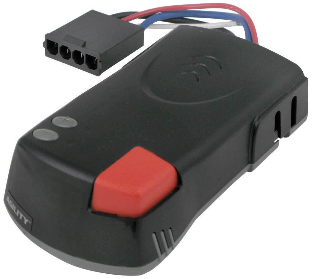
3. wire by using a circuit tester and probing for the wire Adjust the brake control to the desired angle and tighten screws until snug. CAUTION: Using larger/longer screws may damage the unit. Agility™ Electronic Brake Control IMPORTANT: Read the following instructions carefully before installing and/or operating the brake control. If

Genuine Impulse Brake Controller 071610 | EKG DIESEL
The Universal Wiring Adapter for Hopkins Trailer Brake Controllers # HM47685 you asked this from will allow you to connect a wiring harness to your Hopkins brake controller (if that is what you have) to give you the wire leads to splice into your brake light switch and connect your power wire to battery and brake output wire to your 7-way.
Hopkins 47235 Impulse; Electronic Brake Control | eBay
7-Pin Connector. This Curt Trailer Brake Controller Wiring Diagram version is far more appropriate for sophisticated trailers and RVs. It can transfer electricity better hence the connector is suggested for higher-level electric in the car. Here is the diagram for 7-pin connector. White Pin for the floor.
50 Impulse Trailer Brake Controller Wiring Diagram ...
Route blue wire from brake control to vehicle side. This car is designed not just to travel one place to another but also to take heavy loads. Elegant Of Impulse Trailer Brake Controller Wiring Diagram Hopkins Diagram Wire Tekonsha Wiring harness to install hopkins impulse brake controller in a toyota i have a toyota 4runner …

Tekonsha Brake Controller Wiring Diagram - Drivenheisenberg

Wiring Diagram For Trailer Lights With Electric Brakes

Hopkins Impulse Trailer Brake Controller Wiring Diagram ...

8 Practical Impulse Trailer Brake Wiring Diagram Solutions ...

56 Impulse Brake Controller Wiring - Wiring Diagram Harness

Impulse Trailer Brake Controller Wiring Diagram | Trailer ...

56 Impulse Brake Controller Wiring - Wiring Diagram Harness

Curt Trailer Brake Controller Wiring Diagram | Trailer ...

Sabaviva

Hopkins Impulse Trailer Brake Controller Wiring Diagram ...

Wiring Diagram For A Trailer Brake Controller | Trailer ...

Wiring For Trailer Brakes - Hopkins Impulse Trailer Brake ...

Hopkins Impulse Trailer Brake Controller Wiring Diagram ...

Need to create a highlite texture map, for a project I was working on for Sony PlayStation. So I spray painted a brand new controller. After the project was complete I had these extra shots I did not use, in the spirit of Unsplash I decided to upload them.

Hopkins Impulse Trailer Brake Controller Wiring Diagram ...

Wiring Diagram For A Prodigy Brake Controller

Hopkins Reliance Brake Controller Wiring Diagram - Wiring ...
Brake Controller Wiring Schematic
Impulse Trailer Brake Controller Wiring Diagram ...
How To Install the Circuit Breakers From Brake Controller ...
0 Response to "40 impulse brake controller wiring diagram"
Post a Comment