42 autometer air fuel gauge wiring diagram
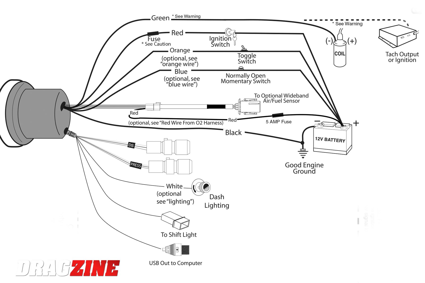
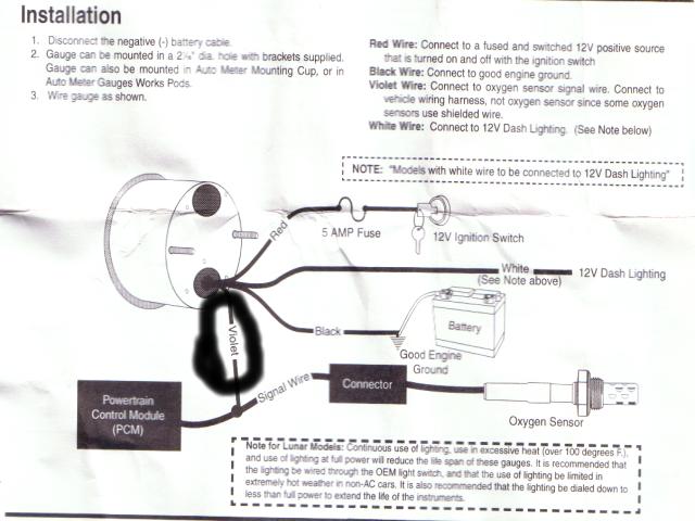
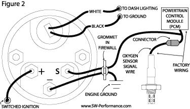
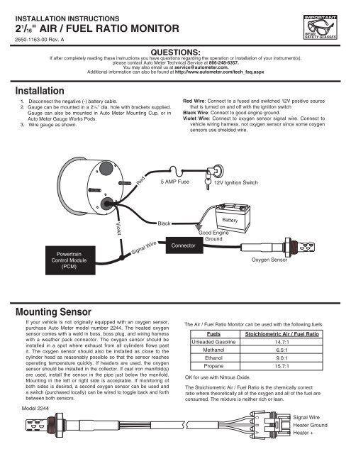
Gauge can be mounted in a 21⁄16" dia. hole with brackets supplied. Gauge can also be mounted in Auto Meter Mounting Cup, or in Auto Meter Gauges Works Pods. Wire gauge as shown. Red Wire: Connect to a fused and switched 12V positive source that is turned on and off with the ignition switch. Black Wire: Connect to good engine ground. Installation Instructions for Auto Meter Cobalt Air/Fuel Ratio Gauge - Digital ... Connect to vehicle wiring harness, not oxygen sensor since some oxygen ...
18 gage, wire from fuel tank to gauge. If a new hole is drilled in the firewall a grommet is recommended. Connect one end to terminal post on fuel level sender and the opposite end to the sender (S) terminal spade on back of gauge. 2. Connect ground wire from ground post on gauge to suitable chassis ground. 3.

Autometer air fuel gauge wiring diagram
Sep 10, 2021 · Wiring diagram for auto meter new wiring diagram auto gauge a newbie s overview of circuit diagrams. Toll free tech support. Pin On Gauges . Higginbotham fuel gauge wiring diagram rate fuel gauge wiring autometer gauge wiring diagram additionally wiring diagram provides you with enough time frame by which the assignments are to be accomplished. Autometer Boost Gauge Wiring Diagram. How to Install an Auto Meter Pro-Comp Ultra-Lite Air/Fuel Ratio Gauge - Electric on Your M or wiring diagram for your specific vehicle to learn which wire is the signal. WARNING. Do not connect ohm meter to oxygen sensor, or touch wire to ground or power. Damage to oxygen sensor will result. diagramweb.net ... Nov 30, 2020 · Autometer Gauge Wiring Diagram – auto meter gas gauge wiring diagram, autometer amp gauge wiring diagram, autometer boost gauge wiring diagram, Every electric structure consists of various unique pieces. Each part should be placed and linked to other parts in specific manner.
Autometer air fuel gauge wiring diagram. You may use 18g or 20g stranded wire for all fuel level gauge wiring. S = This connects to the sending unit in the fuel tank. **(See Sending Unit Wiring Section) I = Supply 12v, key on power to this terminal. It is recommended to use a 3 Amp automotive fuse when supplying power to this ... Therefore Auto Meter offers gauges in many resistance ... 16" WIDE BAND AIR/fUEL RATIO mONITOR ® 2650-1143-00 Rev. A Installation 1. Disconnect the negative (-) battery cable. 2. Gauge can be mounted in a 21⁄ 16” dia. hole with brackets supplied. Gauge can also be mounted in Auto Meter Mounting Cup, or in Auto Meter Gauge Works Pods. 3. Wire gauge as shown. 12V Ignition Switch Good Engine Ground plug, and wiring harness with a weather pack connector. The oxygen ... components available on your Auto Meter Wideband Air/Fuel gauge:. Fuel Level. 1. Gauge connects to fuel sender on fuel tank. Existing wires may be used, or route proper length of 18 gage, wire from fuel tank to gauge. If a new hole is drilled in the firewall a grommet is recommended. Connect one end to terminal post on fuel level sender and the opposite end to the sender (S) terminal spade on back of gauge. 2.
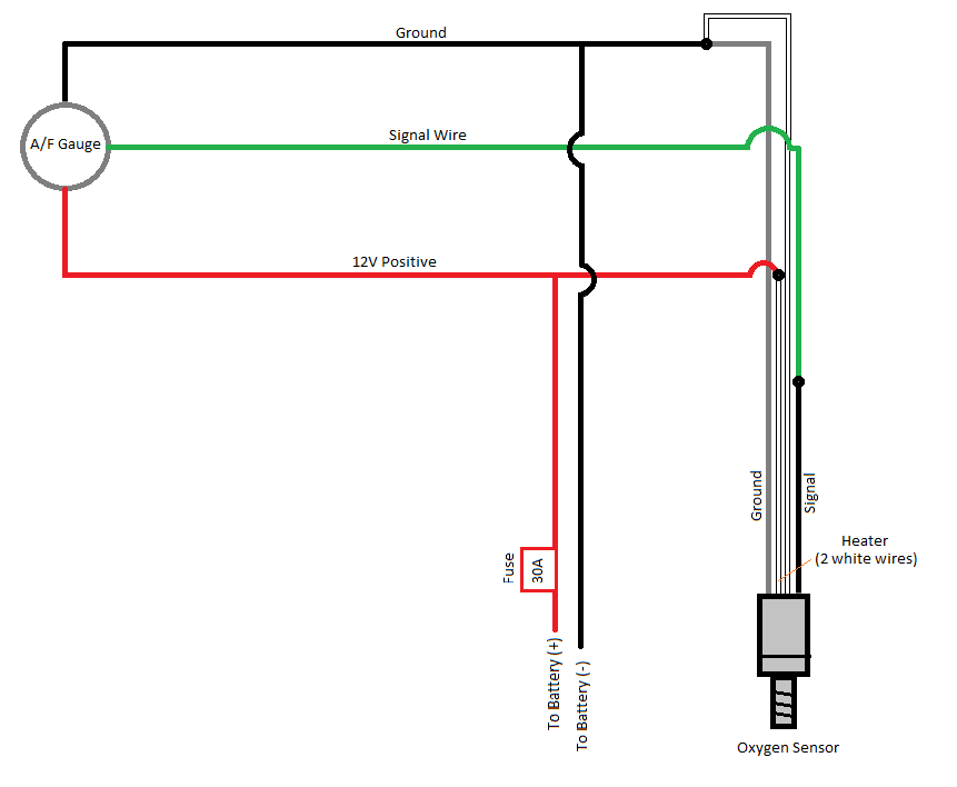
May 20, 2021 · Autometer wideband wiring diagram. Autometer wideband wiring diagram 11 12 2018 11 12 2018 3 comments on autometer wideband wiring diagram auto meter cobalt wideband air fuel ratio gauge analog all i found that the factory oxygen sensor wiring was a secure location to. The Auto Meter Air/Fuel gauge has a signal output for supplying information to a Data Logger or engine management system. The signal provided is a linear 0-4 volts output. 0 volts out equals 10.0 Air/Fuel Ratio, 4 volts out equals 18.0 Air/Fuel Ratio. Note: Due to the limitations of the sensor, the indicated Air/Fuel Ratio Autometer Air Fuel Gauge Wiring Diagram Rate Fuel Gauge Wiring – Autometer Gauge Wiring Diagram. Additionally, Wiring Diagram provides you with enough time frame by which the assignments are to be accomplished. You will be able to learn exactly once the projects should be completed, that makes it easier for you to correctly manage your time ... Nov 30, 2020 · Autometer Gauge Wiring Diagram – auto meter gas gauge wiring diagram, autometer amp gauge wiring diagram, autometer boost gauge wiring diagram, Every electric structure consists of various unique pieces. Each part should be placed and linked to other parts in specific manner.
Autometer Boost Gauge Wiring Diagram. How to Install an Auto Meter Pro-Comp Ultra-Lite Air/Fuel Ratio Gauge - Electric on Your M or wiring diagram for your specific vehicle to learn which wire is the signal. WARNING. Do not connect ohm meter to oxygen sensor, or touch wire to ground or power. Damage to oxygen sensor will result. diagramweb.net ... Sep 10, 2021 · Wiring diagram for auto meter new wiring diagram auto gauge a newbie s overview of circuit diagrams. Toll free tech support. Pin On Gauges . Higginbotham fuel gauge wiring diagram rate fuel gauge wiring autometer gauge wiring diagram additionally wiring diagram provides you with enough time frame by which the assignments are to be accomplished.
Auto Meter Wideband Air / Fuel Ratio Gauges
How To Adjust the Fuel Gauge Sender : How-To Library : The MG ...

2-1/16
Hands-On: Effective Data Logging Through An Autometer Tachometer
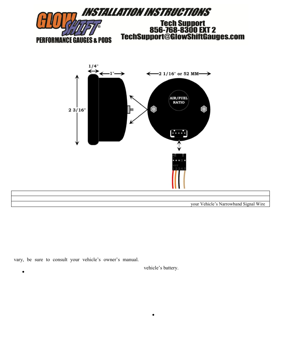
GlowShift Digital Series Narrowband Air_Fuel Ratio Gauge User ...
How to Install Auto Meter Oil Pressure Gauge - Electrical ...

DIY Air / Fuel Ratio Meter

Auto Meter C2 Series Gauges
Please Help With Air/Fuel Gauge Install - MY350Z.COM - Nissan ...

AutoMeter Wideband Gauge Install - REV J HD
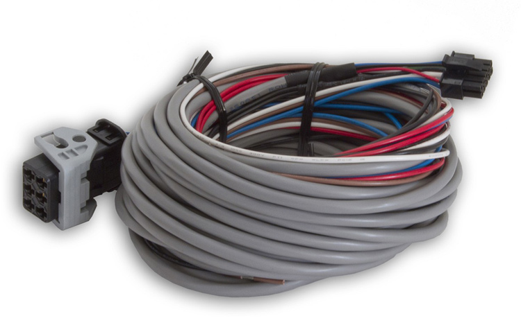
Autometer Wire Harness Extension 25 ft., Wideband Air / Fuel Ratio, Pro
How to Install an Air Fuel Gauge - My Pro Street

Autometer Sport-Comp 52mm Wideband Air/Fuel Gauge - 3378

SpridgetGuru.com-Tech Index-Fuel Gauge Wiring Diagram
Installation mounting Sensor
How-to: Tuning Carbs with an Oxygen Sensor and A/F Gauge ...

MTX-L Digital Air/Fuel Ratio Gauge User Manual - PDF Free ...

How to Install an Air Fuel Gauge - My Pro Street

Autometer GS Series Pro Wideband Air/Fuel Ratio Gauge (6:1-20 ...
air/fuel ratio gauge - HomemadeTurbo - DIY Turbo Forum

2-1/16

Classic Style 60-160 VDC Voltmeter | Electric Car Parts Co
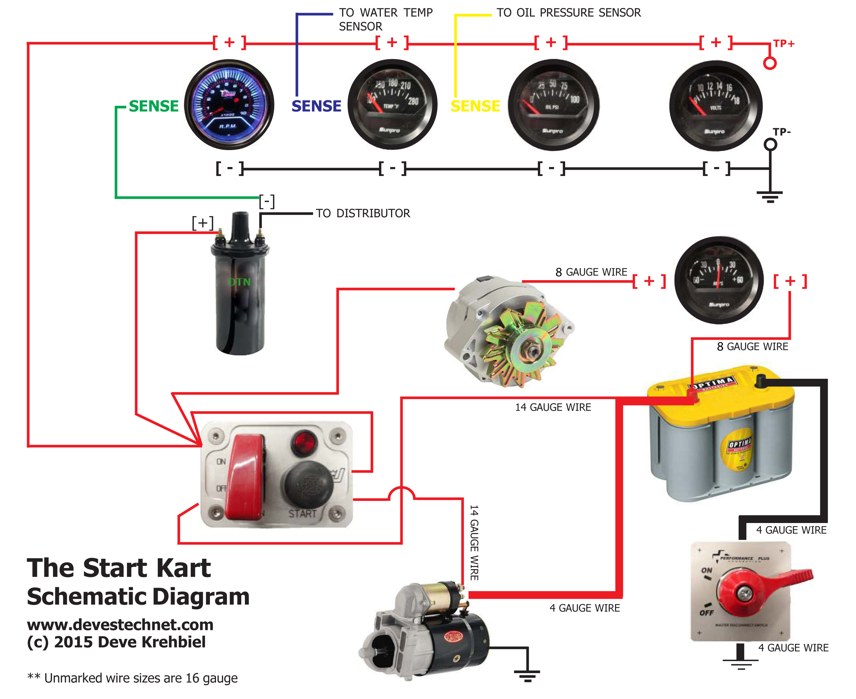
Start Kart Plans

2-1/16
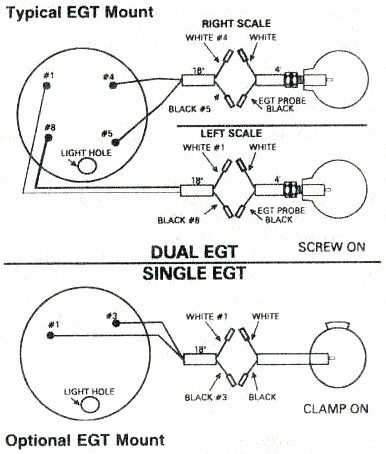
EGT, exhaust gas temperature gauge, Westach, Westberg exhaust ...
Short Sweep Electric Crash Course - Autometer

Amazon.com: Auto Meter 3370 Sport-Comp Wide Band Air Fuel ...

2-1/16

2-1/16" WIDEBAND, AIR/FUEL RATIO, ANALOG, 8:1-18:1 AFR, C2

AutoMeter 1350 Arctic White 5 Gauge Set Fuel/Oil/Speedo/Volt ...

Air/Fuel Ratio Gauge

Autometer Air Fuel Ratio Gauge Wiring Diagram the purpose of ...
21/16" AIR / fUeL RATIO mONITOR Installation ... - Auto ...
Auto Meter : User Manual

2-1/16

How do I hook up a Autometer Tach to my 2003 Chevy Cavaleir ...

2-1/16

Air/Fuel Ratio Gauge

2-1/16" WIDEBAND AIR/FUEL RATIO, ANALOG, 8:1-18:1 AFR, SPORT ...

Adjustable Fuel Gauge Tube-Type Fuel Sender | Installation ...
Installation

2-1/16" WIDEBAND PRO AIR/FUEL RATIO, 6:1-20:1 AFR, NV
0 Response to "42 autometer air fuel gauge wiring diagram"
Post a Comment