42 fe cr phase diagram
The Mo additions were mainly Figure 7 shows an isothermal section of the Fe-Cr-N aimed to improve the alloy oxidation resistance according equilibrium diagram at 1473 K,[22] as well as the phase to the Schaeffler's diagram (i.e., Mo increases the chro- diagram for binary Fe-Cr system. Notice from this diagram mium equivalent). that Fe-Cr ... Determination of the Fe-Cr-Ni and Fe-Cr-Mo Phase Diagrams at Intermediate Temperatures using a Novel Dual-Anneal Diffusion-Multiple Approach Cao, Siwei; Abstract. Phase diagrams at intermediate temperatures are critical both for alloy design and for improving the reliability of thermodynamic databases. There is a significant shortage of ...
The phase diagram for the common end members of the olivine solid solution series shows that pure forsterite melts at 1890 o C and pure fayalite melts at 1205 o C. Thus, the olivines are sometimes seen be be zoned from Mg-rich cores to more Fe-rich rims, although such zoning is usually limited to 5 to 10% difference between the cores and the rims.

Fe cr phase diagram
Binary phase diagrams show the complete convex hull for the system, where the y-axis is the formation energy per atom and the x-axis is the composition (e.g. in the \(\ce{Fe-P}\) phase diagram, the x-axis is the fraction of \(\ce{P}\)). Figure 2: Calculated Fe-P Phase Diagram FTmisc - FACT Sulfide, Alloy, Micellaneous Phase Diagrams. Click on a system to display the phase diagram. Fe + Cr Nb + MO + Si Figure 3. Psuedo-Equilibrium Ternary Solidification Diagram for A718 Showing Solidification Path Direction from y to y t A,B Laves Phase (After Reference 5) Figure 3 also indicates that higher levels of Nb, MO, and Si promote the formation of Laves phase.
Fe cr phase diagram. Download scientific diagram | 1: Fe-Cr phase diagram (a) [18]; Fe-Cr-0.1C phase diagram (b) [19]. from publication: Alloy development for high Cr martensitic steel | Martensite, Steel and Alloys ... Description. Phase diagram of Fe-Cr-.2%C.svg. English: Isopleth of ternary phase diagram of Fe-Cr-C at a constant 0.2 % C. The horizontal axis is mass percentage of Cr. This diagram was made by the uploader based on the figure in the following secondary source: 田中 良平(編). 2010『ステンレス鋼の選び方・使い方』改訂 ... Phase diagrams for FE-CR-NI based alloys. Part 1: Phase diagrams for binary and ternary alloys of FE, CR and NI with C and with SI. EU publications. Download Order. Aug 01, 2013 · In the present Co–Cr–Fe–Mn–Ni alloys, no phase separation was observed, even though they were furnace-cooled from homogenization temperatures. This can be understood based on two reasons. First, in HEA, the high mixing entropy enhances the mutual solubility between elements and the stability of solution phases [76] .
the ternary phase diagram with respect to the aus-tenite stabilized region in the low Cr composition has not beenentirely identified evenin the recent st.udy. Thepurpose of this study is to investigate the eq,ui-librium phasediagram of Fe-Cr-Mnsystem at 923 K (650'C), in particular, to examine the extent of a single phase reg_ion in the low Cr ... binary and ternary phase diagrams of Al(acac) 3-Cr(acac), Cr(acac) 3-Fe(acac) 3, Al(acac) 3-Fe(acac) 3 and Al(acac) 3-Cr(acac) 3-Fe (acac) 3 were constructed and their eutectic temperatures were determined. The eutectic temperature was obtained at 1: 1 ratio for its binary systems. From the binary phase diagram, ternary phase diagram was ... 金属やセラミックスの状態図、エンリンガム図などの情報を提供しています。 一部、不確かなものもありますので、自己 ... 金属やセラミックスの状態図、エンリンガム図などの情報を提供しています。 一部、不確かなものもありますので、自己 ...
by T Barkar · 2018 · Cited by 4 — The behaviour originates from a miscibility gap in the Fe-Cr phase diagram. The boundary of the miscibility gap is denoted the binodal, and the ...56 pages Jan 15, 2022 · The nano-scaled structure of the Fe/Cr-rich A2 and Ni/Al-rich B2 phases with an almost constant modulation width of approximately 10–15 nm was interpreted to be the result of the strong interaction energies in the Fe-Cr pair and Ni-Al pair during liquid-phase spinodal decomposition from an undercooled melting. 3) Isothermal phase diagram of Fe-Cr-O system at 1 600°C was established. The relationshp between the chromium content of Fe-Cr melt and the oxide phase equilibrated was determined. below 1% Cr-cubic chromite, 1-7%Cr-c/a=1-0.95 above 7% Cr-Cr2O3 The goal of the Jacobs School Student and Faculty Racial Equity Task Force is to make the Jacobs School a truly inclusive community. The Task Force, which kicked off in 2020 along with the first cohort of Racial Equity Fellows, is tasked with developing a comprehensive understanding of existing programs and resources in place to reach this goal, and suggesting solutions where …
The binary Fe-Cr phase diagram [17]. | Download Scientific ...
Phase Diagram Resources from ASM International. Alloy phase diagrams and crystal structure data are used by metallurgists, materials engineers, and materials scientists to develop new alloys for specific applications; fabricate these alloys into useful configurations; design and control heat treatment procedures for alloys that will produce the required mechanical, …

Alloys of 30 Zinc
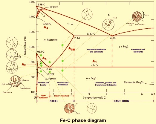
Iron-Carbon Phase Diagram. The iron-carbon phase diagram is widely used to understand the different phases of steel and cast iron. Both steel and cast iron are a mix of iron and carbon. Also, both alloys contain a small amount of trace elements. The graph is quite complex but since we are limiting our exploration to Fe3C, we will only be ...
Carbon Steels and the Iron-Carbon Phase Diagram ...
192 / Phase Diagrams—Understanding the Basics. A hypothetical ternary phase space diagram made up of metals . A, B, and . C. is shown in Fig. 10.2. This diagram contains two binary eutectics on the two visible faces of the diagram, and a third binary eutectic between ele-ments . B. and . C. hidden on the back of the plot. Because it is ...
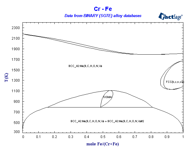
BINARY (SGTE) Alloy Phase Diagrams
The re-calculated phase diagram of the Fe-Cr system based on the present study is shown in Fig. 1. As expected, the FCC γ-loop is observed on the Fe-rich side. The BCC phase has a large miscibility gap between Fe-rich (BCC) and Cr-rich (BCC') alloy compounds. σ phase is stable at elevated temperatures. Download : Download high-res image (105KB)

Ni Laboratory
ternary phase diagram of Ni-Cr-Fe. MSE 2090: Introduction to Materials Science Chapter 9, Phase Diagrams 11 Isomorphous system - complete solid solubility of the two components (both in the liquid and solid phases). Binary Isomorphous Systems (I) Three phase region can be identified on the phase diagram:
Ferro-Chrome - IspatGuru
For example, the first figure below is the T(C) versus Wt.% C phase diagram of the Fe-Cr-C system at 2.8 Wt.% Cr calculated under normal equilibrium conditions (orthoequilibrium). Data are taken from the SGTE 2011 databases. The second figure is the paraequilibrium diagram for the same system when C is the only diffusing component.

Skyscraper HD. Skyline Rosario.
Ternary phase diagram books by D.R.F. West – there are several . Ternary grid . Space diagram . C A B . Space diagram . Usually have elements at the corners as the constituents, ... For diagrams where there is a major . component, e.g. Fe in Fe-C-Cr, use a . …

Quasi-binary phase diagrams: a-the Fe 40 Mn 25 Cr 20 Ni 15 ...
The experimental phase diagram of the Fe-Cr-Al alloys has two sections, the Fe-Cr rich section in which Fe-Cr solid solution is stable [21] and the Al rich section in which ternary intermetallic phases exist [22].At 1000°C, no ternary intermetallic phase was found experimentally in the Al-corner region [23].

Fe-Cr-Ni pseudo-binary phase diagram at 63% Fe (Ref 10 ...
It is evident from Figure 6 (Fe-Cr-C phase diagram) that typical martensitic steels should exhibit ferrite and M 23C 6in equilibrium at for example, 600°C. In practice, this carbide is only found after relatively long ageing. because it is preceded by Intermediate phases in the sequence cementite, M 2X and M 7C 3, leading finally to M 23C 6.

Thermodynamic Properties of Li-LiH (LiD, LiT) Systems. The ...
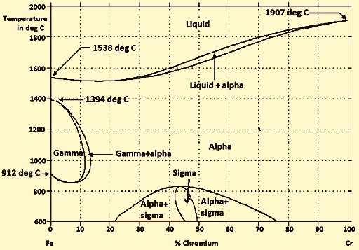
English: The different version of File:Diagramme phase Fe Cr.svg.The horizontal axis label has been changed to English, and the blank space has been reduced. According to the description of File:Diagramme phase Fe Cr.svg, this diagram was made based on the source "Phase diagramme iron-chromium as per BAIN and ABORN - Metals handbook, American Society for Metals, 1948, 1194".

Pseudobinary section of the Fe-Cr-Ni ternary phase diagram ...
Fe-Cr Co-Cr Lo-133 950 -115 950 L1 31 000 10 800 L2-127 000 -95 000 Phase diagrams with intermetallic sigma phase of Fe-Cr and Co-Cr systems described by proposed model, have been presented as an example in [13,14] in very good agreement with experimental phase equilibrium data [8-11].

IN718 nickel-based superalloy held for 24 hours at 850°C
Journal of Phase Equilibria - 76Mir: D. A. Mirzaev, N.M. Mirzaeva, and Kh.M. Ibragimov, “The Fe-Cr-C Phase Diagram in the(Fe γ Cr γ)7C 3 Region,≓Sb. Nauchni.

-Metastable phase diagrams of (a) Fe-N-C, (b) Fe-Cr-N-C ...
Cr-C phase diagram [9] A Fe-Cr-C ingot with the cross section line A-A' Chemical composition of phases by EDS (at.%) The cross-sectional microstructure of the ingot reconstructed based on images...

Zn-Fe - Phase Diagram
The phase diagrams and elastic properties of the Fe-Cr-Al alloys in full-temperature and all-compositional ranges are calculated. By combining first-principles calculations and cluster variation method, binary and ternary phase diagrams are obtained.

IN718 nickel-based superalloy held for 72 hours at 850°C
Phase diagram of Fe--Cr--Co permanent magnet system (Conference) | OSTI.GOV Phase diagram of Fe--Cr--Co permanent magnet system Abstract The miscibility gap of the ..cap alpha.. phase in Fe-Cr-Co permanent magnet alloys is constructed using mechanical hardness and Curie temperature measurements.
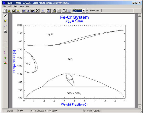
FactSage.com - Phase Diagram module
The Fe-Cr-Mo phase diagram contains two solid solutions (bcc (α) and fcc (γ)), four binary intermetallic compounds/phases (the σ, μ, λ (the Laves phase) and R phases), and one ternary phase (the χ (Chi) phase which was denoted as τ 1 in the early literature and in Ref 5 ).
![a Schaeffler diagram [15] and b section of ternary Fe-Cr ...](https://www.researchgate.net/profile/Ismail_Hemmati/publication/225729017/figure/download/fig1/AS:393758559490048@1470890764022/a-Schaeffler-diagram-15-and-b-section-of-ternary-Fe-Cr-Ni-phase-diagram-Composition-of.png)
a Schaeffler diagram [15] and b section of ternary Fe-Cr ...
24.07.2020 · The phase transition from non-magnetic (NM) to ferromagnetic (FM) phase was observed at a T c ~ 220 K for 30 nm, T c ~ 215 K for 12 nm and T c ~ 170 K for 5 nm, respectively. The ferromagnetism ...
Phase diagram of a bulk Fe-V alloy system [36]. | Download ...
1273K-C-Cr-Fe FSstel: 1273K-C-Fe-Mn FSstel: Ag-Al FScopp: Ag-Al FTlite: Ag-Al SGnobl: Ag-Al SGTE 2014: Ag-Al SGTE 2017: Ag-Al SGTE 2020: Ag-Al-Au_500C SGnobl: Ag-Al-Bi_870C SGnobl: Ag-Al-In_650C SGnobl: Ag-Al-Mg_liquidus SGnobl: Ag-Al-Pb_870C SGnobl: Ag-Al-Si_500C SGnobl: Ag-Al-Si_liquidus SGnobl. Ag-Al-Sn_25C SGnobl: Ag-Al-Sn_liquidus SGnobl ...

Ternary diagram for the Fe-Cr-Ni system at 400°C ...
Thermodynamic study of phase diagrams and minimisation of the Gibbs free energy ... Demonstrations and working examples: Two cases (Cu-Ni and Fe-Cr systems)-3-What is an equilibrium phase diagram? 1.1. Definition and experimental determination of an equilibrium phase diagram
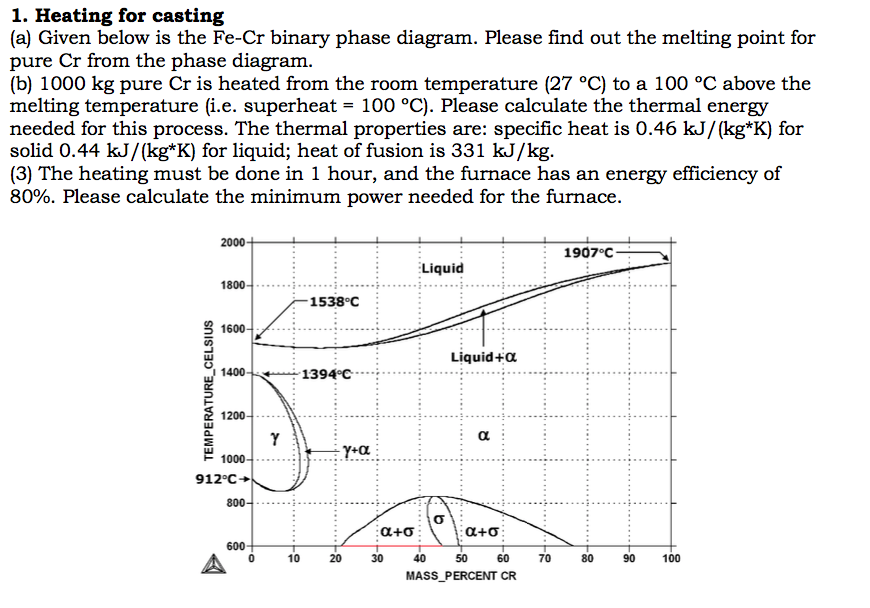
(a) Given below is the Fe-Cr binary phase diagram. | Chegg.com
Iron -chromium phase diagram Fe-Cr phase diagram shows which phases are to be expected at equilibrium for different combinations of chromium content and temperature. The phase diagram of the Fe-Cr binary system is at Fig 1. The melting point of Fe and Cr is taken at the pressure of 1 atmosphere as 1538 deg C and 1907 deg C respectively.

IN718 nickel-based superalloy held for 1 minute at 850°C
Phase diagram Ab initio Fe-Ni Fe-Rh Al-Cr-Fe abstract The standard magnetic model in the current CALPHAD modeling is based on the Inden-Hillert-Jarl model and an empirical constraint due to Weiss and Tauer that can be used to connect ferromagnetism and antiferromagnetism. In this work, we demonstrate that many artifacts can be produced by using

The Fe-Cr phase diagram Í‘ Ref. 20 Í’ . Note that the phase ...
Cr Si Mn W Mo Review Fe-C phase diagram • 2 important points-Eutectoid (B): γ⇒α+Fe 3C-Eutectic (A): L ⇒γ+Fe 3C Fe 3 C (cementite) 1600 1400 1200 1000 800 600 400 0 12 3 4 5 66.7 L γ (austenite) γ+L γ+Fe 3C α+Fe 3C α + γ L+Fe 3C δ (Fe) C o, wt% C 1148°C T(°C) α 727°C = Teutectoid A R S 4.30 Result: Pearlite = alternating ...

IN718 nickel-based superalloy held for 6 hours at 850°C
02.06.2021 · 4.6: Pourbaix Diagrams Last updated; Save as PDF Page ID 183315; No headers. Pourbaix Diagrams plot electrochemical stability for different redox states of an element as a function of pH. As noted above, these diagrams are essentially phase diagrams that map the conditions of potential and pH (most typically in aqueous solutions) where different redox …

Partial 18 pct Cr-Fe-N diagram, showing the --Cr 2 N phase ...
Phase Diagram. このサイトを検索 ... Fe-Cr. Data from RICT-Sol alloy database ver.1.0. Sign in | Recent Site Activity | Report Abuse | Print Page | Powered By Google Sites ...
Martensitic Stainless Steel for Knife Applications - Part ...
Fe + Cr Nb + MO + Si Figure 3. Psuedo-Equilibrium Ternary Solidification Diagram for A718 Showing Solidification Path Direction from y to y t A,B Laves Phase (After Reference 5) Figure 3 also indicates that higher levels of Nb, MO, and Si promote the formation of Laves phase.

Al-Zn - Phase Diagram
FTmisc - FACT Sulfide, Alloy, Micellaneous Phase Diagrams. Click on a system to display the phase diagram.

IN718 nickel-based superalloy held for 48 hours at 850°C
Binary phase diagrams show the complete convex hull for the system, where the y-axis is the formation energy per atom and the x-axis is the composition (e.g. in the \(\ce{Fe-P}\) phase diagram, the x-axis is the fraction of \(\ce{P}\)). Figure 2: Calculated Fe-P Phase Diagram

Cr-Fe Phase Diagram and Database (GeDb for FactSage)
![A calculated [5] Fe-Cr phase diagram, together with the ...](https://www.researchgate.net/profile/Ville_Valtteri_Visuri/publication/344267021/figure/download/fig1/AS:938439688069122@1600752865736/A-calculated-5-Fe-Cr-phase-diagram-together-with-the-experimental-data-points-31Adc.png)
A calculated [5] Fe-Cr phase diagram, together with the ...

A calculated Fe-Cu phase diagram, together with the ...
1: Fe-Cr phase diagram (a) [18]; Fe-Cr-0.1C phase diagram ...

Phase diagram of the Fe-Si-Cr ternary system at 873 K [9 ...

Minerals and phase relations in the Fe-Ni-Ir ternary ...
Wooden barrels outside a shop in downtown Santa Fe, NM

sothermal Fe-Cr-C phase diagram calculated at 1573 K by ...
Analysis of the Precipitation and Growth Processes of the ...

Fe-Cr - Phase Diagram

Isothermal section of the Fe-Cr-Ni ternary phase diagram ...

Constitution diagram for the Fe-Cr system Í‘ see Ref. 1 Í’ ...

Liquidus projection for the Fe-Cr-C ternary system [12-15 ...
Martensitic Stainless Steel for Knife Applications - Part ...

Fe-Cr Phase Diagram | Diagrama
0 Response to "42 fe cr phase diagram"
Post a Comment