38 grease trap piping diagram
Grease Separators G Series G-C Series GF Series RTO Series GIS Series Grease Separator Sizing Installation Diagrams Grease Separator Cleaning Rep Search Contact Us Protect waste lines against blocking and stoppages. Select a separator with a gallon-per-minute flow equal to the initial tank discharge capacity. Draw-off valve available. With an internal flow control, an external […] Grease Interceptor Sizing and Installation Guidelines E-102 Grease protection is an essential element for restaurants, cafes, catering facilities, commissaries, hotels, cafeterias, convenience stores, full service grocery stores, schools, hospitals, and food manufacturing plants.
Pumps and Piping ... Sanitary Waste and Vent Piping ... Traps and Interceptors
Grease trap piping diagram
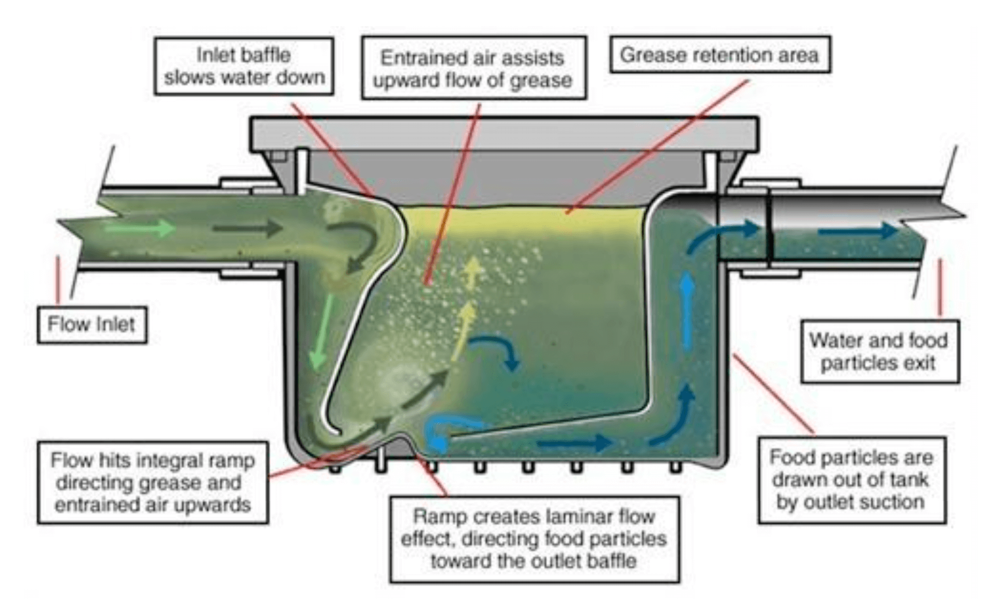
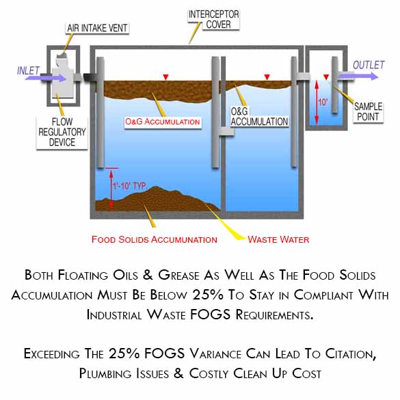
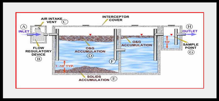
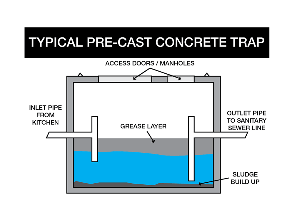
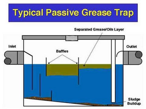
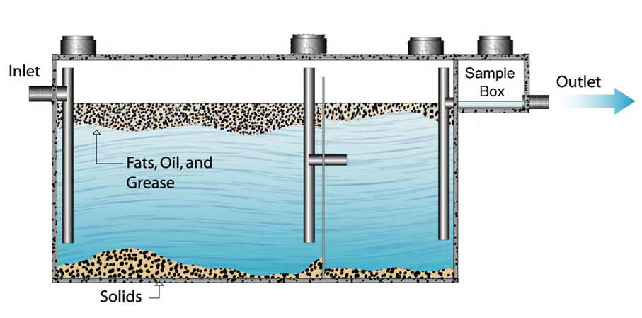
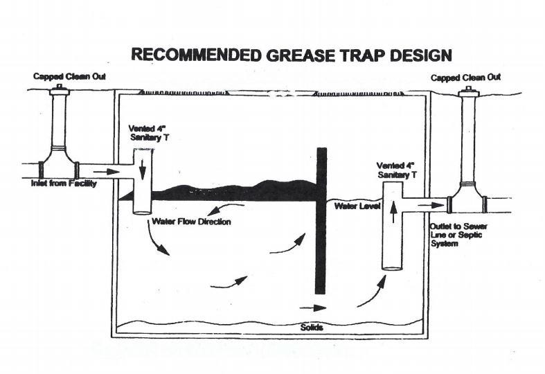
Grease traps usually consist of an underground, watertight, concrete tank with baffled inlet and outlet piping. The outlet pipe has a tee that allows the internal discharge to be located within 0.3 m of the tank bottom. The size of the grease trap depends on the anticipated flow rate, water temperature, and grease concentration. 46 25 23 - Grease Traps. 46 25 00 - Oil and Grease Separation and Removal Equipment. 46 25 13 - Coalescing Oil-Water Separators. Remove Filter. Default Recent. 43 CAD Drawings for Category: 46 25 23 - Grease Traps. The definition of a grease trap is " a trap in a drain or waste pipe to prevent grease from passing into a sanitary sewer lines and system." A grease trap/grease inceptor is in simple terms a plumbing fixture that contains decomposing food waste, bettering the sewer system. There are three main types of grease traps:
Grease trap piping diagram. The International Plumbing Code (IPC) 1002.1 (exception 3) allows a grease interceptor to serve as a fixture trap - where it is intended by the manufacturer to serve as a trap - for a single fixture or a combination sink of not more than three compartments so long as the vertical distance from the outlet of the fixture to the inlet of the interceptor is not more than 30 inches and the ... Get the best grease trap removal services from Premier Grease ... Grease Trap, Perangkap Lemak Dapur, Grease Trap Biofive Call Us Today to Learn More About Grease Trap Repair Services Lincoln City OR ... It does not matter if the pipes are made out of steel, copper or ... The diagrams of the devices are from the 2000 ... tions for the grease trap, grease interceptor and grease and sand interceptor are diagrammatic only. The size and design of these devices or apparatus is depend- ... HEALTH ASPECTS OF PLUMBING 92 93 Grease interceptor. This type of device is usually installed outside the building
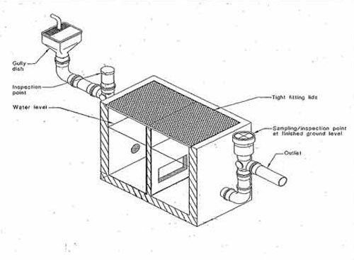
piping in the grease trap should be sufficient to allow gravity-differential separation to the grease so that it will not escape hrough t e ou tle. The minimu horizontal distance shall be twenty-four inches. M104.12 Access/Covers 04.12.1 Access from the top of the grease trap shall be ... diagram that illustrate a grease interceptor (similar ... In order to clean a grease trap or a grease interceptor properly, JR Grease Services, Inc. 4. Grease traps must be installed in the plumbing system for restaurants and businesses that prepare food. The location and size of the grease interceptors must be included on the isometric drawing. For further information see the Building Inspections handout titled Grease Interceptors in Kitchens. 5. Diagram A OPERATION OF GREASE INTERCEPTORS SIZING The Plumbing and Drainage Institute (PDI) as well as some national and local codes have recognized different ways of sizing grease interceptors. It is advisable to check with local authorities for sizing requirements in your particular locality.
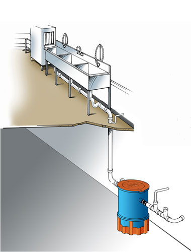
Grease trap must be piped in accordance with the diagram below. ... For more information our range of grease traps, get in contact with W & M Kiely ... ... grease traps – Dependent on the ... Here are two diagrams that show where the grease collects within the trap until it’s time to be removed. Internal (Under the Sink) Grease Trap Diagram Vent Pipe Must be lower than sink drain Flow Restrictor Grease Trap . FLC SERIES AppROVED SINKS OPTIONAL p _ TRAP VENT (AIR INTAKE) CLEANOUT FLOW ORIFICE PLATE INLET VENT OUTLET VENT FLOW CONTROL ZURN LICHT COMMERCIAL SERIES 2700 INTERCEPTOR . Title: Microsoft Word - Document1 Author: mar06302 ... Your pipes will soon be clear of accumulated hair and soap scum. ... Recommended Plumbing Contractor Atherton CA A burst pipe can create damage that ...
Fats, Oils, and Grease Disposal - Capital Region Water
and similar equipment and to prevent grease accumulations from clogging connecting piping and sewer lines. In 1883, one Nathaniel T. Whiting of California applied for a patent on a grease trap, which was issued in October of 1884. Whiting's design principle was not unlike that of present day grease interceptors.

APPENDIX A: GREASE INTERCEPTOR AND GREASE TRAP SIZING
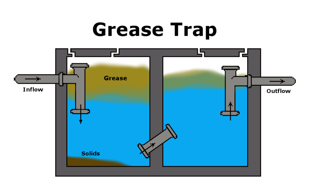
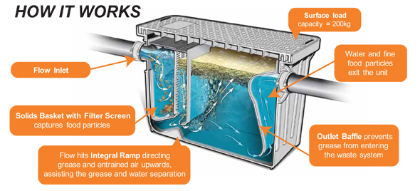
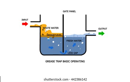
Simply put, a grease trap is a system within a drain or waste pipe to prevent grease from entering the wider sewer system.

Grease traps help protect pipes but have a dangerous side
Manual grease trap designs date back to the Victorian days. Nathaniel Whiting was the first person to obtain a patent for a grease trap. Grease traps are usually constructed from stainless steel or plastic and must be cleaned occasionally. How To Install A Residential Grease Trap
Grease Trap & Interceptor Service Houston, TX | Southwaste
Any commercial store or restaurant that prepares food needs a grease trap to separate FOG (Fats, Oils and Greases) from water that is returned to ...
Grease Interceptor Selection Services | Plumbing | NY Engineers
Grease traps and the contributing plumbing configuration must be approved by the City of Bloomington Utilities Department prior to installation. For more information, please contact the CBU Pretreatment Program Inspector at 812-349-3934.

Grease Interceptor 30 LB / 15 GPM
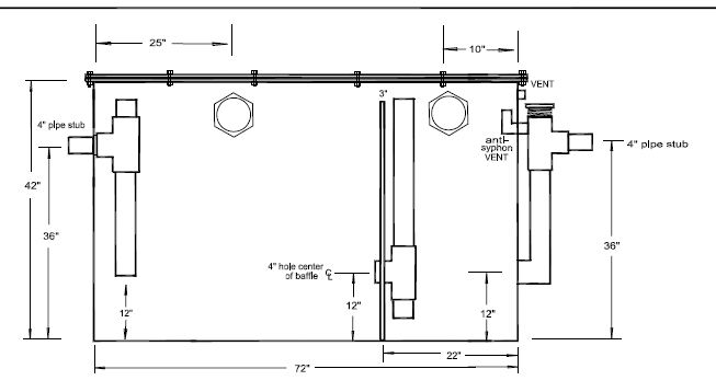
XL Grease Trap 75 GPM - CAD Drawing 1. XL Grease Trap 75 GPM - CAD Drawing 2 - In Ground Installation. XL Grease Trap 75 GPM - CAD Drawing 3. XL Grease Trap 75 GPM - CAD Drawing 4 - Not Traffic Rated. XL Grease Trap 75 GPM - CAD Drawing 5 - In- Ground Installation M-Rated Cover.
Chapter 5: Traps, Cleanouts, Interceptors, and Backwater ...
We stand behind the quality of our products and will make things right if you are not satisfied. All products sold from Drain-Net have a 1 year limited warranty from date of purchase against defects in material or workmanship, under normal use.
Grease Traps | Hukill's Inc., Medford
Grease Trap and Interceptor Maintenance Grease trap maintenance is usually performed by maintenance staff, or other employees of the establishment.

Grease Interceptor Sizing and Installation Guidelines ...
Diagram illustrating the effluent pipes from the student cafeteria, one into the grease trap, the other bypassing the trap.
Grease Trap Cleaning | Restaurant Grease Trap Pumping Service
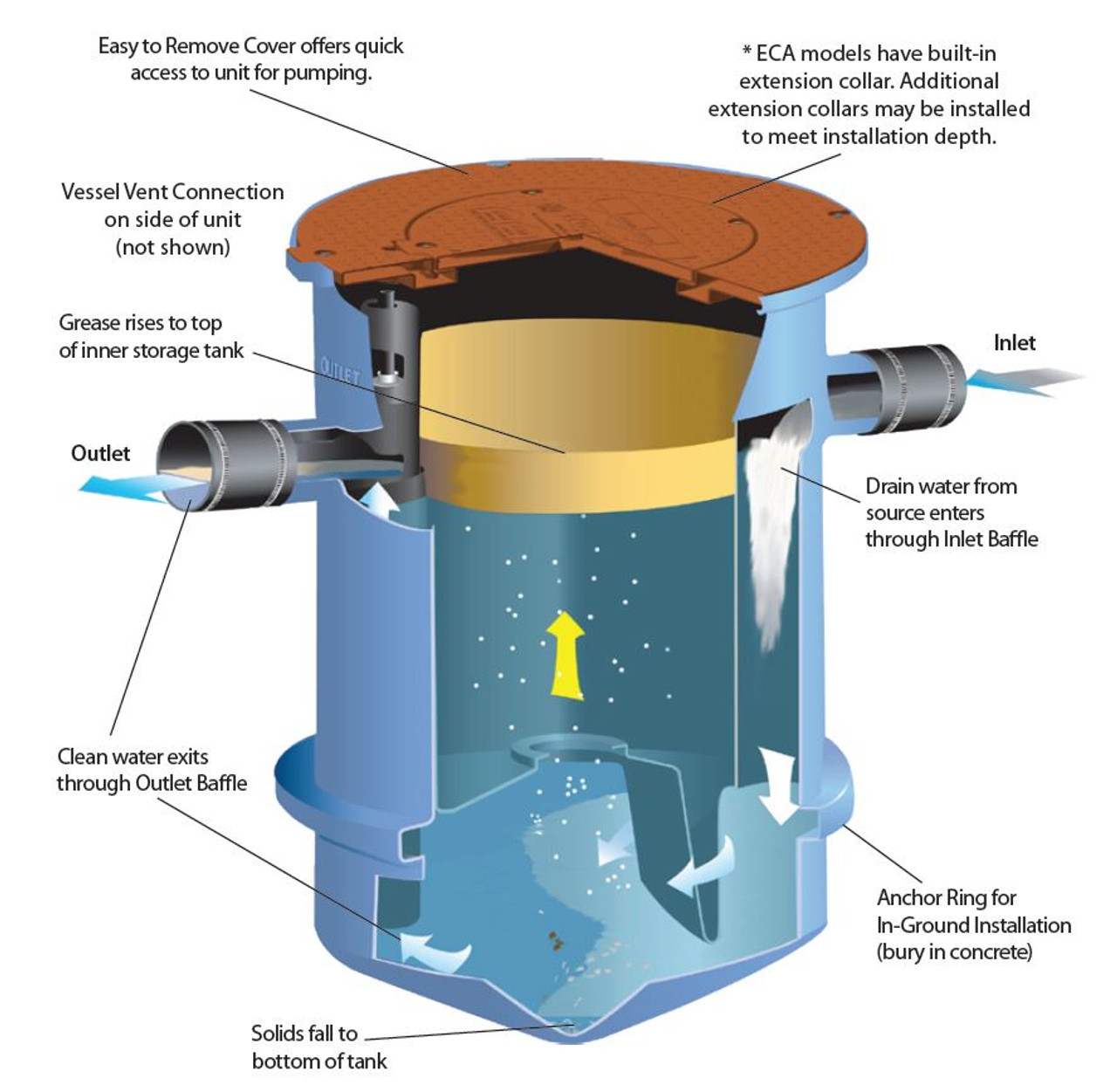
Piping Connections All Endura Grease Interceptors are manufactured with no hub connections. Standard mechanical joint couplings can be used to connect the grease interceptor to a metal or plastic piping system. If the piping system needs tobe resized, use appropriate mechanical joint reducers, but do notdecrease pipe diameter across the unit.

F.O.G (Fats, Oils & Grease) – City of De Soto
the grease and water layers downward toward the bottom of the interceptor (Diagram E). If pressure continues to build, grease would eventually be forced under the baffle plate and out of the unit. The presence of a vented flow control device and air relief by-pass is a key element in the efficient operation of a grease interceptor. If one

Grease Trap Pumping Services | Sewer and Drain Cleaning | B&P ...
• The plumbing code does not prohibit discharge of a food waste disposer downstream of the interceptor. • Mixed reviews on this: - Studies have indicated that dishwasher prerinse sinks are a significant source of grease and food waste grinders are often installed with the prerinse sink - Since a food waste grinder operates best with a cold

Grease traps - installation requirements | Manualzz
The definition of a grease trap is " a trap in a drain or waste pipe to prevent grease from passing into a sanitary sewer lines and system." A grease trap/grease inceptor is in simple terms a plumbing fixture that contains decomposing food waste, bettering the sewer system. There are three main types of grease traps:

Grease Traps? Fuhgeddaboudit! IF you have the right grease ...
46 25 23 - Grease Traps. 46 25 00 - Oil and Grease Separation and Removal Equipment. 46 25 13 - Coalescing Oil-Water Separators. Remove Filter. Default Recent. 43 CAD Drawings for Category: 46 25 23 - Grease Traps.
Custom Grease Traps
Grease traps usually consist of an underground, watertight, concrete tank with baffled inlet and outlet piping. The outlet pipe has a tee that allows the internal discharge to be located within 0.3 m of the tank bottom. The size of the grease trap depends on the anticipated flow rate, water temperature, and grease concentration.
Trapzilla Grease Interceptor, 4" Inlet/Outlet, 75 GPM Flow ...
Grease Interceptors | James City County, VA
Trapzilla | What is a Grease Trap
How a Grease Trap Works - Nitschke Liquid Waste
Grease Trap Cleaning in Toledo, OH | Grease Trap Pumping

How Do Grease Traps Work?, Long Island, NY
COLLIER TOWNSHIP MUNICIPAL AUTHORITY GREASE REMOVAL ...
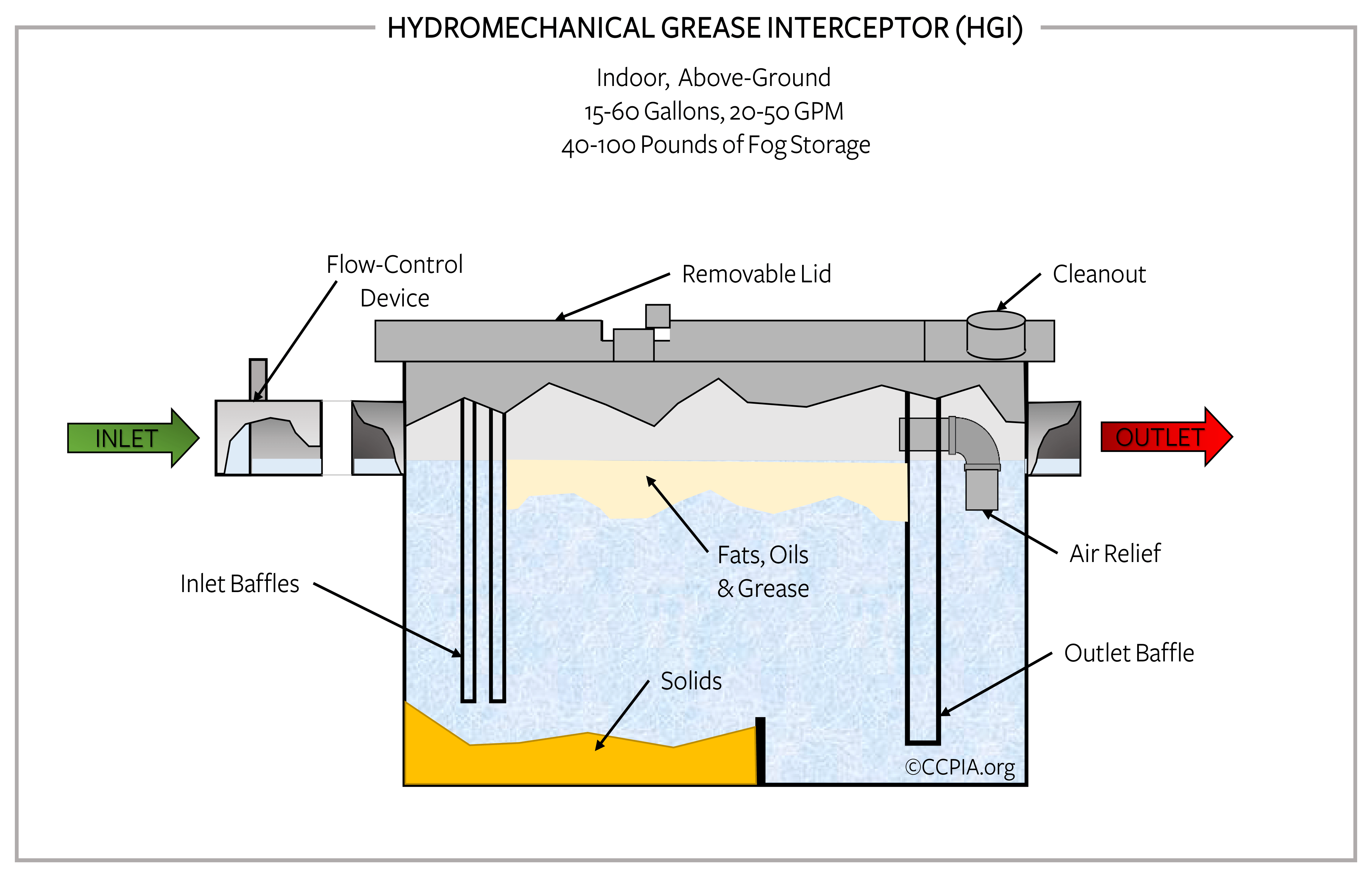
Grease Trap Inspection - CCPIA
How Grease Trap Cleaning Works | Sweet Honey

A) Schematic diagram of a traditional grease trap (two ...
cleaning grease trap

Grease trap - Wikipedia
Grease Trap And Interceptor Cleaning - Ameriguard Maintenance ...

Grease Trap Cleaning In Des Moines IA - Interceptor Services
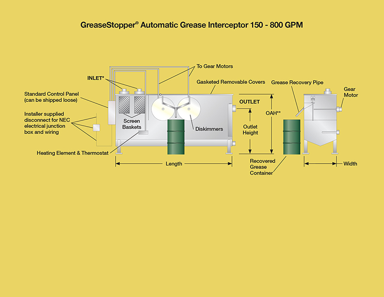
grease interceptors automatic - Highland Tank

Jensen Precast - Gravity Grease Interceptors - Standard

Grease Trap Installation NJ • Grease Interceptor Installation NJ

Fig. S1 Diagram of the grease trap in the experiment ...
Grease Pumping - Alpha Omega Plumbing & Septic

Grease Traps And Grease Interceptors - Wastewater Treatment
Grease trap Images, Stock Photos & Vectors | Shutterstock
Grease traps help protect pipes but have a dangerous side
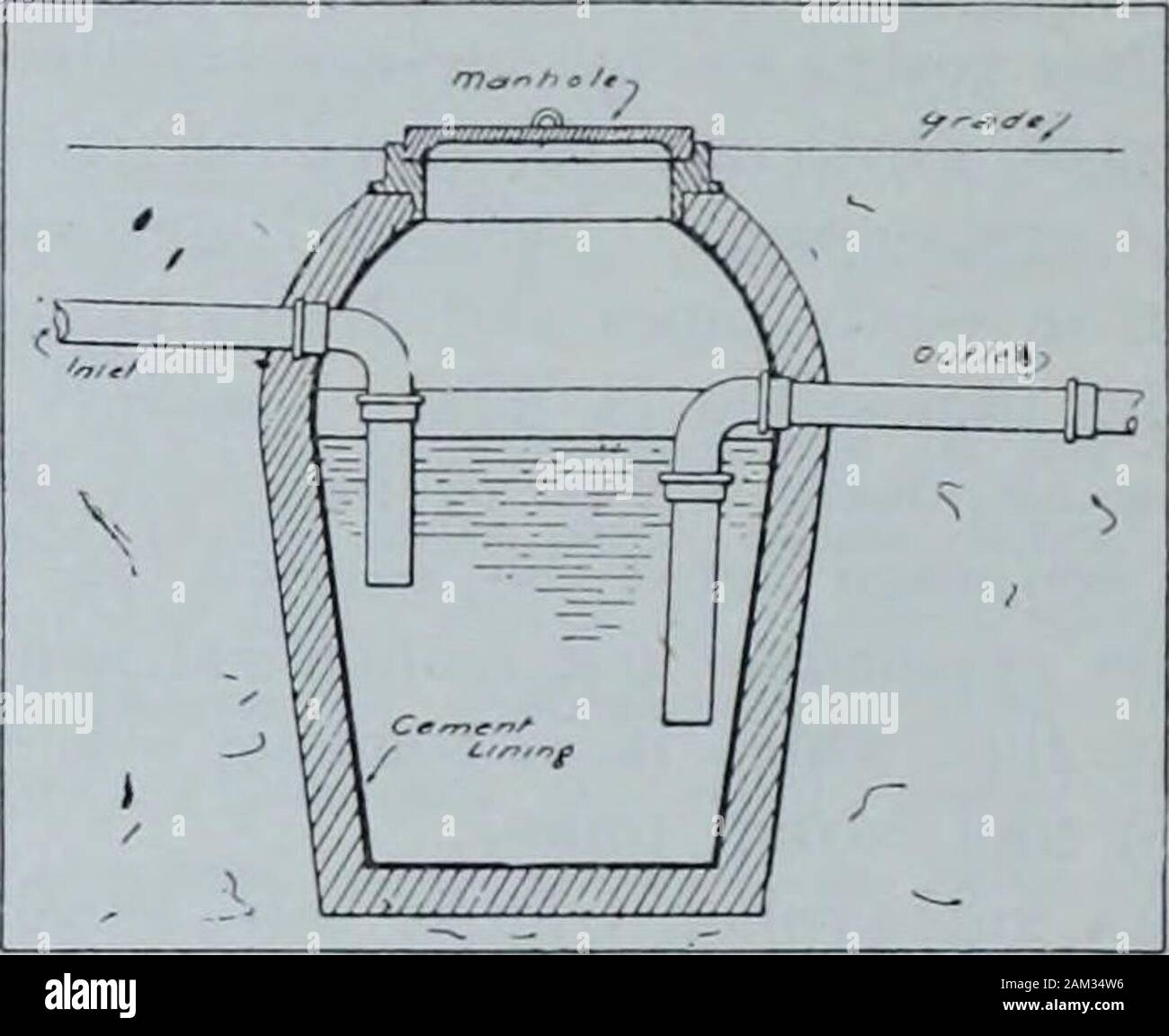
Mechanical Contracting & Plumbing January-December 1908 . e ...
0 Response to "38 grease trap piping diagram"
Post a Comment