39 where is the resistor located on this diagram points 3
How to Connect a Ballast Resistor - DoItYourself.com The best location for the ballast resistor to be connected is close to the coil along the firewall. This will not only give you a better attachment point, but also keep you from having to run wires all over the engine compartment. Choose a location near the coil and mark your placement. Step 3: Drill Holes for Securing Resistor PDF Circuit A Circuit B - Livingston Public Schools A 50.-ohm resistor, an unknown resistor R, a 120-volt source, and an ammeter are connected in a complete circuit. The ammeter reads 0.50 ampere. 9) Calculate the equivalent resistance of the circuit shown. 10) Determine the resistance of resistor R shown in the diagram. Resistors in series OR could use KLR : ' ' ' ' ' ¦ ' 190
Resistor Color Code Calculator - 4 band, 5 band, 6 band ... The resistor color code calculator makes it easy to identify and select resistance and tolerance values for 4, 5, and 6 band through hole resistors.

Where is the resistor located on this diagram points 3
Physics Test #1 Concepts Flashcards - Quizlet A resistor R is connected to the terminals of a battery with a potential difference V. As a result of the connection, a direct current I passes through the resistor. If the resistor is replaced by a different resistor with a resistance R/3, what effect, if any, will there be on the current passing through the resistor? Electrical resistance and conductance - Wikipedia Points on the current–voltage curve located in the 2nd or 4th quadrants, for which the slope of the chordal line is negative, have negative static resistance. Passive devices, which have no source of energy, cannot have negative static resistance. However active devices such as transistors or op-amps can synthesize negative static resistance with feedback, and it is used … Using 8:1 Multiplexers to Implement Logical Functions 05/03/2018 · We won’t go into this in detail here. Suffice it to say that we ended up with the truth table and circuit diagram illustrated below: (Source: Max Maxfield. Earlier, we noted that we can use the CD4512’s 8:1 multiplexer to implement any 3-input logical function. In this case, however, we have a 4-input function. Is there any way we can use a ...
Where is the resistor located on this diagram points 3. Ballast Resistor Wiring Diagram Points – Wiring Sample Nov 04, 2021 · Diagram attached for wiring of points dizzy and coil with ballast resistor. Diagrams show the points connected to the SPOUT pin which must mean it is pulled up to 12V internally with a resistor. Bypass any resistance unit to provide full 12V key ON power to the. Coil figure 1 unilite wiring diagram using ballast resistor note. 1.The diagram below represents a lamp, a 10-volt battery, 4 ... 2.The diagram below shows a circuit with three resistors. What is the resistance of resistor R3? 3.Base your answer to the following question on the diagram below, which shows two resistors and three ammeters connected to a voltage source. A)10.0 A B)6.0 A C)3.0 A D)4.0 A Science help! 1. According to the diagram where is the ... The resistor is located at the point D in the given diagram. 2). The switch is located at the point B in the given diagram. Explanation: A resistor in a circuit is a component that opposes the flow of current through the circuit. SOLVED: Where is the location of the blower motor resistor ... Here's a link to the blower motor resistor,these resistors control the blower motor speed,when they go out,they won't work or work on 1 or 2 speeds,autozone will take back if it doesn't solve problem.Easy to remove,they are located by blower motor,just remove electrical connector and 2 screws.Here's where the blower motor is.Here's the blower ...
SparkFun Inventor's Kit Experiment Guide - v4.0 - learn ... 07/01/2014 · The SparkFun Inventor's Kit (SIK) is your map for navigating the waters of beginning embedded electronics. This guide contains all the information you will need to build five projects encompassing the 16 circuits of the SIK. PDF Electricity Review-Sheet Name: Date - The Leon M ... 3. In the resistor shown, 24 joules of work is done in moving 6.0 coulombs of charge from point A to point B. What is the electrical potential between A and B? A. 12 volts B. 48 volts C. 3.0 volts D. 4.0 volts 4. Electrical power is measured in units called A. watts B. joules C. volts D. amperes 5. A negatively charged rod is brought in contact ... Physics Exam Flashcards - Quizlet Two point particles with charges +3 μC and +5 μCare held in place by 3-N forces on each charge inappropriate directions. Find the distance between the charges..21. ... In the diagram, the current in the 3-Ω resistor is 4 A. The potential difference between points 1 and 2 is: 20v. SOLVED: Were is the HVAC resistor located? - Fixya the blower motor is located under the passenger side of the dash. The blower motor resistor is located behind the glove box assembly. You will need to remove the glove box assembly and then you will see the resistor. It will have one connector with four or five wires and will be held to the HVAC unit with 2 screws.
Electric Circuits Review - Answers #3 - Physics Classroom Even if the circuit is a parallel circuit, any point between the positive terminal of a battery and light bulb will have the same electric potential; and any point located between the - terminal of the battery and a location after passage through the resistor of a branch have the same electric potential. feedburner.google.com Nous voudrions effectuer une description ici mais le site que vous consultez ne nous en laisse pas la possibilité. In the diagram the current in the 3 \u2126 resistor is 4 A ... In the diagram, the current in the 3-Ω resistor is 4 A. The potential difference between points 1 and 2 is: A) 0.75 V B) 0.8 V C) 1.25 V D) 12 V E) 20 V Ans: E Difficulty: M Section: 27-6 20. Solved 11. In the diagram, the current in the 3-S2 ... 11. In the diagram, the current in the 3-S2 resistor is 8 A. The potential difference between points 1 and 2 is: 302 2 A) 0.75 V B) 0.8 V C) 1.25 V D) 12 V Dann E) 40 V ; Question: 11. In the diagram, the current in the 3-S2 resistor is 8 A. The potential difference between points 1 and 2 is: 302 2 A) 0.75 V B) 0.8 V C) 1.25 V D) 12 V Dann E) 40 V
Three resistors are connected as shown in the diagram.Through ...
PDF run through a ballast resistor or wire. Bypass any Pins #3&6 are tied together and hooked to the positive side of the coil. That should be keyed ignition power. ... run through a ballast resistor or wire. Bypass any resistance unit to provide full 12V key ON power to the ... diagrams show the points connected to the SPOUT pin which must mean it is pulled up to 12V internally with a

Duet 3 Tool Board - Duet3D
What is Power System? Definition ... - Circuit Globe Definition: The power system is a network which consists generation, distribution and transmission system.It uses the form of energy (like coal and diesel) and converts it into electrical energy. The power system includes the devices connected to the system like the synchronous generator, motor, transformer, circuit breaker, conductor, etc.
Search Results - Media Directory Search | Bosch Rexroth AG
Simpson Model 260 Volt-Ohm-Milliammeter - Library of Congress 3!" round. acc urac y . 2~ ·clear·vue sc ale len gt h: 1-7/8" bu ilt to special order . also as models 125, 135 . 2p. 3p. it!". 5!" sizes . 145 and 155 - all 2!" round . sc ale . 1-7/8 " models 27, 37.57 illuminate d . 3!" rectang ular accu rac y: 2$ sc ale le ng th : 1-5/ 16" ~ r~1,~ 7 ~ iiiiiiiii (® i!!i!li . models 29,39,49,59 . models ...

Understanding Common-Mode Signals | Maxim Integrated
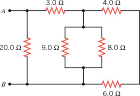
Solved Five resistors are connected as shown in ... - Chegg The potential difference between points A and B is 15 V. 8. What is the equivalent resistance between the points A and B? 9. What is the current in the 3.6-ohm resistor? 10. What is the current in the 2.7-ohm resistor? Question: Five resistors are connected as shown in the diagram. The potential difference between points A and B is 15 V. 8.

Fixed Resistor - an overview | ScienceDirect Topics
Basic simple electrics for model railways - Eastbank Gaps should be located as shown and the three wires installed as on the diagram. That's not the only way to do it. If you only have set track points, again dead or alive, without the facility of fitting an accessory switch, don't despair, there is a solution. Once again the gaps are located as shown but this time across each gap is fitted a ...

JMSE | Free Full-Text | Complete Coverage Path Planning of an ...
Kirchhoff’s Rules | Physics - Lumen Learning The junction rule. The diagram shows an example of Kirchhoff’s first rule where the sum of the currents into a junction equals the sum of the currents out of a junction. In this case, the current going into the junction splits and comes out as two currents, so that I 1 = I 2 + I 3. Here I 1 must be 11 A, since I 2 is 7 A and I 3 is 4 A. Kirchhoff’s Second Rule. Kirchhoff’s second rule ...

Where is the resistor located on the diagram? - Brainly.com
Where is the resistor located on the diagram? - Brainly.com Dec 07, 2018 · The spring A …. opposite measures 8 cm. It lengthens. 1 cm for each 100g mass that is suspended at its end. The spring B measures 5 cm and extends by 1 cm for each 75g mass that is suspended at its end. It is possible to suspend the same mass to these two springs so that they are of the same length, once extended.
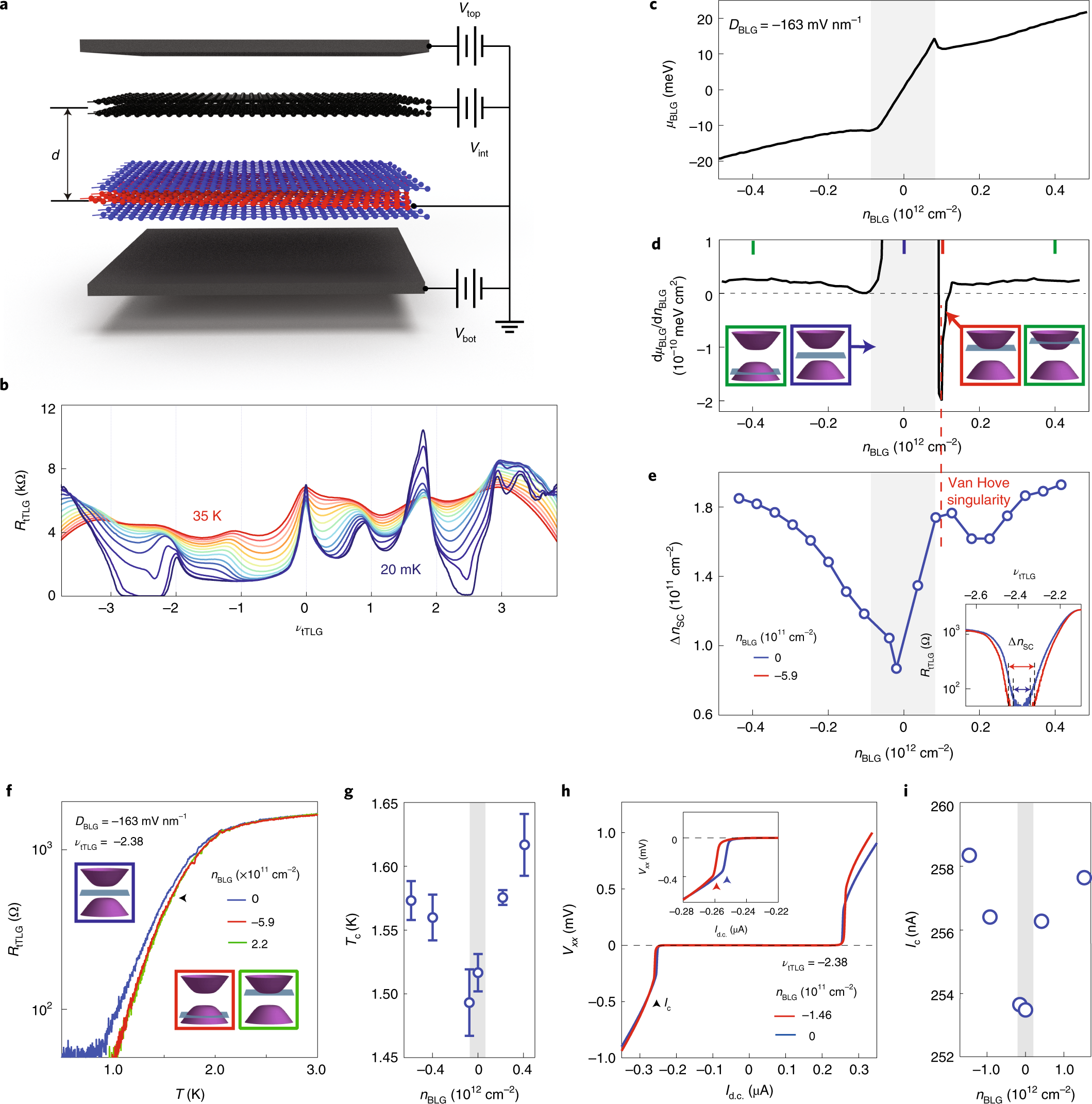
Isospin order in superconducting magic-angle twisted trilayer ...
What is a Resistor? Construction, Circuit Diagram and ... For example, a carbon film resistor is taken to give details of the construction of a resistor. The construction of a resistor is shown in the below diagram. This resistor consists of two terminals like a normal resistor. The construction of a carbon film resistor can be done by placing the carbon layer on a substrate of a ceramic.
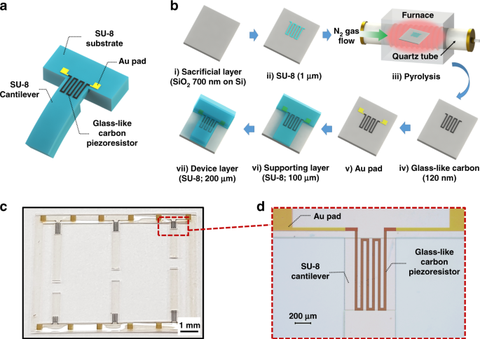
SU-8 cantilever with integrated pyrolyzed glass-like carbon ...
3 Pin Variable Resistor Diagram Mar 12, 2018 · What does the 3 pin on the circuit diagram of this motor mean. A potentiometer can be linear or. Switch optional a potentiometer or pot for short is also known as a variable resistor. There are 3 pinsterminals on a preset. As shown in the diagram below a variable resistor consists of a track which provides the resistance path.

Lesson Explainer: Series Circuits | Nagwa
Electrical diagrams for Chrysler, Dodge, and Plymouth cars This wiring diagram is for the 1980 and later four pin ignition module. If you have an ignition harness with five wires, just don't connect the dark green wire that would go to pin 3. I Installed a Jacobs computer ignition, and it doesn't require a ballast resistor. I don't know, but I think MSD, Accel, and others are the same.
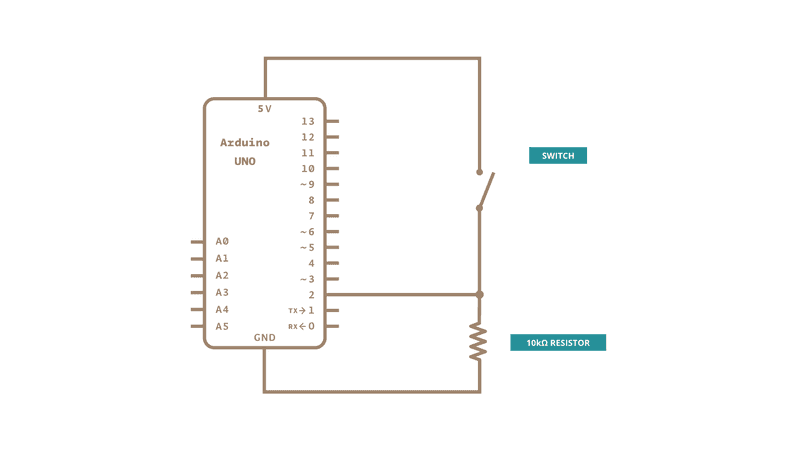
Button | Arduino
SOLVED: Where is the blower motor resistor located on 1992 ... 20,706 Answers. Re: Where is the blower motor resistor located on 1992... If the blow works on high but not lower speeds. this air cooled (housing) resistor is checked first. heater blower housing cooled resistor, Posted on Oct 01, 2016. Helpful 0.

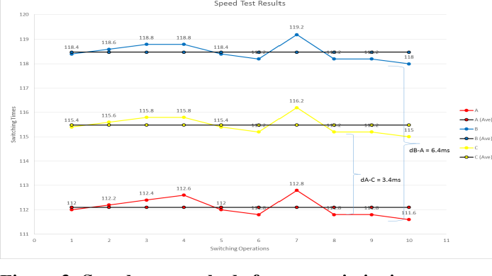
How to Model Statistical Tolerance Analysis for Complex ...
SOLVED: Where is the resistor module located for ... - Fixya the relay is built into the speed resistor or motor control module ) depends if you have automative or manual heater controls. is automatic it will be motor control module and manual is the resistor module. these units are located beside the heate fan motor. the motor helps keeps the unit cool. just unbolt the module, unplug it and install new ...

Keithley Low Level Measurements Handbook - 7th Edition ...
AN-105: Current Sense Circuit Collection ... - Analog Devices AN-105: Current Sense Circuit Collection Making Sense of Current. by Tim Regan, Jon Munson, and Greg Zimmer Download PDF Introduction. Sensing and/or controlling current flow is a fundamental requirement in many electronics systems, and the techniques to do so are as diverse as the applications themselves.

Five resistors are connected as shown in the diagram. The ...
Using 8:1 Multiplexers to Implement Logical Functions 05/03/2018 · We won’t go into this in detail here. Suffice it to say that we ended up with the truth table and circuit diagram illustrated below: (Source: Max Maxfield. Earlier, we noted that we can use the CD4512’s 8:1 multiplexer to implement any 3-input logical function. In this case, however, we have a 4-input function. Is there any way we can use a ...

The circuit diagram given below shows the combination of ...
Electrical resistance and conductance - Wikipedia Points on the current–voltage curve located in the 2nd or 4th quadrants, for which the slope of the chordal line is negative, have negative static resistance. Passive devices, which have no source of energy, cannot have negative static resistance. However active devices such as transistors or op-amps can synthesize negative static resistance with feedback, and it is used …

Discussion between tlfong01 and Circuit fantasist - 2020-11-25
Physics Test #1 Concepts Flashcards - Quizlet A resistor R is connected to the terminals of a battery with a potential difference V. As a result of the connection, a direct current I passes through the resistor. If the resistor is replaced by a different resistor with a resistance R/3, what effect, if any, will there be on the current passing through the resistor?

Resistor - Wikipedia
64.42 -- Resistor cube
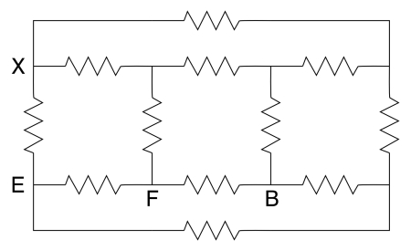
PROBLEM 3 – X points
TriangleWave—Wolfram Language Documentation

Science help! 1. According to the diagram where is the ...

Eaton MEDC BG2 - Heating and Process

File

Two-fluid and finite Larmor radius effects on high-beta ...

Damping resistor current frequency spectrum for series R ...
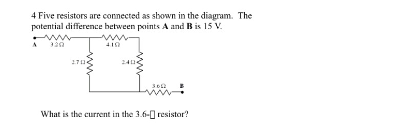
Answered: 4 Five resistors are connected as shown… | bartleby
LX-6 Hand Box Modification

Solved In the diagram, the current in the 3 12 resistor is 4 ...
Classes of tree-based networks | Visual Computing for ...
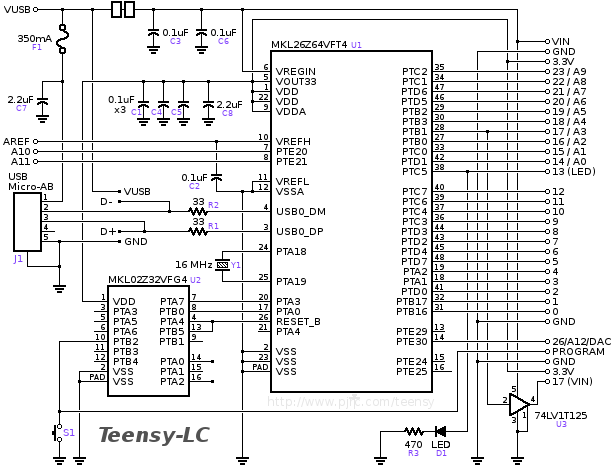
Teensy and Teensy++ Schematic Diagrams
65. ssm Determine the equivalent resistance between the ...
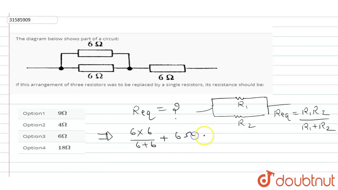
The diagram below shows part of a circuit: If this arrangement of three resistors was to be replaced

3 points for each blank cell in table, 30 points total) The ...

Lesson Explainer: Series Circuits | Nagwa

Diagram of the sensor. The noise resistor is mounted on a ...

Phase current reconstruction of three-level Neutral-Point ...
EMTP-based analysis of pre-insertion resistor and point on ...
Energies | Free Full-Text | A Novel Phase Current ...
Secure Site Shop with Confidence Home What's New Search ...
0 Response to "39 where is the resistor located on this diagram points 3"
Post a Comment