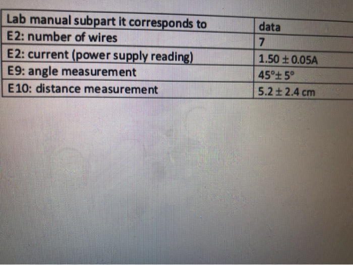
40 draw a top down diagram of your setup from part e
Moving Drawing From TOP View To FRONT VIEW. - Autodesk Moving Drawing From TOP View To FRONT VIEW. Hi guys, I'm new to the forums and this would be my first time posting here. I'm new to autocad and I was looking for an way to move my sketch into the front plane because by mistake instead of sketching it on the front plane I sketched on the top plane. PDF Chapter 4 - Dimensioning Drawings Select the top and left side of the box to create the first rounded corner then repeat the command and select the top and right side of the box. You should be left with the object shown on the right. Now we can draw the folding lines and start projecting the features shown on the front view to the right and top views.
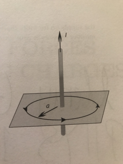
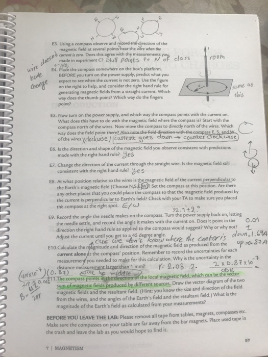
Draw a top down diagram of your setup from part e October 28, 2021 thanh. Draw a top down diagram of your set up. 1. (3.5) Draw a top-down diagram of your setup from part E. This diagram should include: a. The cardinal directions (N,S,E,W) b. The direction of current in the wires c. The direction of the compass needle d. A vector representing the Earth's magnetic field e. A vector representing the wire's magnetic field at the location of the compass f.

Draw a top down diagram of your setup from part e
PDF 3 -View Drawings B - Starting at point #1, draw a diagonal line up to the left 5 intersections. (take your time and hit each diagonal intersection) C - Repeat step B for points 2, 3, 4, and 5. D - Now simply connect all 5 dots and your isometric view will be complete. STEP 4 STEP 5 LENGTH H E I G H T Front View 3" 2 " H E I G H T Top View 1 / 2 " 1 " 3 ... 1. (3.5) Draw a top-down diagram of your setup from | Chegg.com 1. (3.5) Draw a top-down diagram of your setup from part E. This diagram should include: a. The cardinal directions (N,S,E,W) b. The direction of current in the wires c. The direction of the compass needle d. A vector representing the Earth's magnetic field e. A vector representing the wire's magnetic field at the location of the compass f. The vector Solved DATA (3): - Draw a top-down diagram of your setup ... See the answer See the answer done loading. DATA (3): - Draw a top-down diagram of your setup of image provided: I is current passing through wire arrows are vectors of compass pointing. This diagram should include: - The direction of current in the wires - The direction of the compass needle - Vectors representing the Earth's magnetic field and the magnetic field of the wire at the location of the compass - Known and relevant distances,angles, and currents - The cardinal directions (N,S,E,W
Draw a top down diagram of your setup from part e. how to draw a circle inside a square mathematics quarter 1 module 4 grade 8 answer key; 2022.02.17; by ; 0 Drawing in Excel (Examples) | How to use the Drawing Toolbar? To draw anything from shapes in Excel, select any of the shapes we want to draw, hold left-click drag, draw the shape in the size we want, and then release the key to get the final drawing. Start Your Free Excel Course. Excel functions, formula, charts, formatting creating excel dashboard & others. First Angle and Third Angle Projection : 1st angle vs 3rd ... Left side of front view. Right side of front View. To sum up, an orthographic projection system is used to draw a three-dimensional object in the 2D plane. In First angle projection, the object lies in between the 1observer and plane of projection. Whereas in the third angle projection, the projection plane lies in between observer and Object. Network Notepad draw "top box" black_pen0.5 20 10: draw path pen x y [xscale yscale] [angle] Draw the outline of a path using the specified pen. Draw at position and apply an optional local scale transform and/or rotate transform. path - name of path to draw. pen - name of pen to use. x y - position of drawing.
PDF Orthographic Projections Pictorial drawing Perspective drawing Multi-view drawing Difficult to create Easy to visualize. Shape and angle distortion Object looks more like what our eyes perceive. Size and shape distortion Right angle becomes obtuse angle. Circular hole becomes ellipse Distorted width Accurately presents object's details, i.e. size and shape. Require ... React draw curves — #staraakashtech #technology #education ... See drawing above in part (e). 1 point is earned for the correct identification of E a in Step 1 In calculus we had to freehand draw lots of curves up to quintic and what we always did was use basic derivatives to find the zeroes and where each curve is increasing/decreasing and concave up/concave down (this is relatively straightforward ... PDF Chapter 8 Multiview Drawings - McGraw Hill (or essentially so), then the projectors (i.e., projection lines) are parallel and the drawing is classified as a paral-lel projection. (See Figure 8.5.) Parallel projection 378 PART 2 Fundamentals of Technical Graphics requires that the object be positioned at infinity and viewed from multiple points on an imaginary line paral-lel to the object. PDF Three-View, Plan View and Elevation View Drawings TOP View r Front View Right Side View Using the Top View shown in Fig. 2-8 as the Right-Side View, make a second sketch and compare it with Fig. 2-9. The three-view drawings which have been discussed are generally accepted as standard in the United States and TOP View On squared block paper, make a three- view drawing of the concrete block with
Draw a top-down diagram of your setup of image provided: I i This diagram should include: - The direction of current in the wires - The direction of the compass needle - Vectors representing the Earth's magnetic field and the magnetic field of the wire at the location of the compass - Known and relevant distances,angles, and currents - The cardinal directions (N,S,E,W) - Use your measurements from part E to calculate the strength of the Earth's magnetic field. DATA (3): - Draw a top-down diagram of your setup of image ... DATA (3): - Draw a top-down diagram of your setup of image provided: I is current passing through wire arrows are vectors of compass pointing. This diagram should include: - The direction of current in the wires - The direction of the compass needle - Vectors representing the Earth's magnetic field... (PDF) Engineering Drawing by N.D.Bhatt. | kaustubh ubale ... Engineering Drawing by N.D.Bhatt.. × Close Log In. Log in with Facebook Log in with Google. or. Email. Password. Remember me on this computer. or reset password. Enter the email address you signed up with and we'll email you a reset link. Need an account? Click here to sign up. Log In Sign Up. Log In ... Steering System: Types, Parts, Function, Diagram ... The car steering system or just steering system is the most important part in automobile vehicle steering control, respond so well to the driver while driving. Steering control makes you feel safe while driving. The car steering system in the automobile is the process of running the vehicle in the desired direction by turning, usually the front wheels.
Midterm Study Guide - Veterinary Radiology and Ultrasound ...
how to draw a circle inside a square / how to draw a circle inside a square. how to draw a circle inside a square ...

How to Build a Gaming PC: Gaming PC Parts and Step by Step ...
PDF Drafting the Men's Shirt Block - Burda Style Now draw a vertical line above point C to point D, located at the same height as point A. Step 4 — Draw guide line at top Now connect points A and D. Note that this line does not form part of the finished pattern - it is a guide line, and you might want to draw it in less heavily than the finished garment lines. Step 5 — Draw in the waist line

Gallery of Installation Three: Service & Supply Store ...
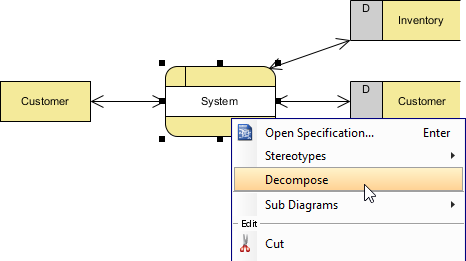
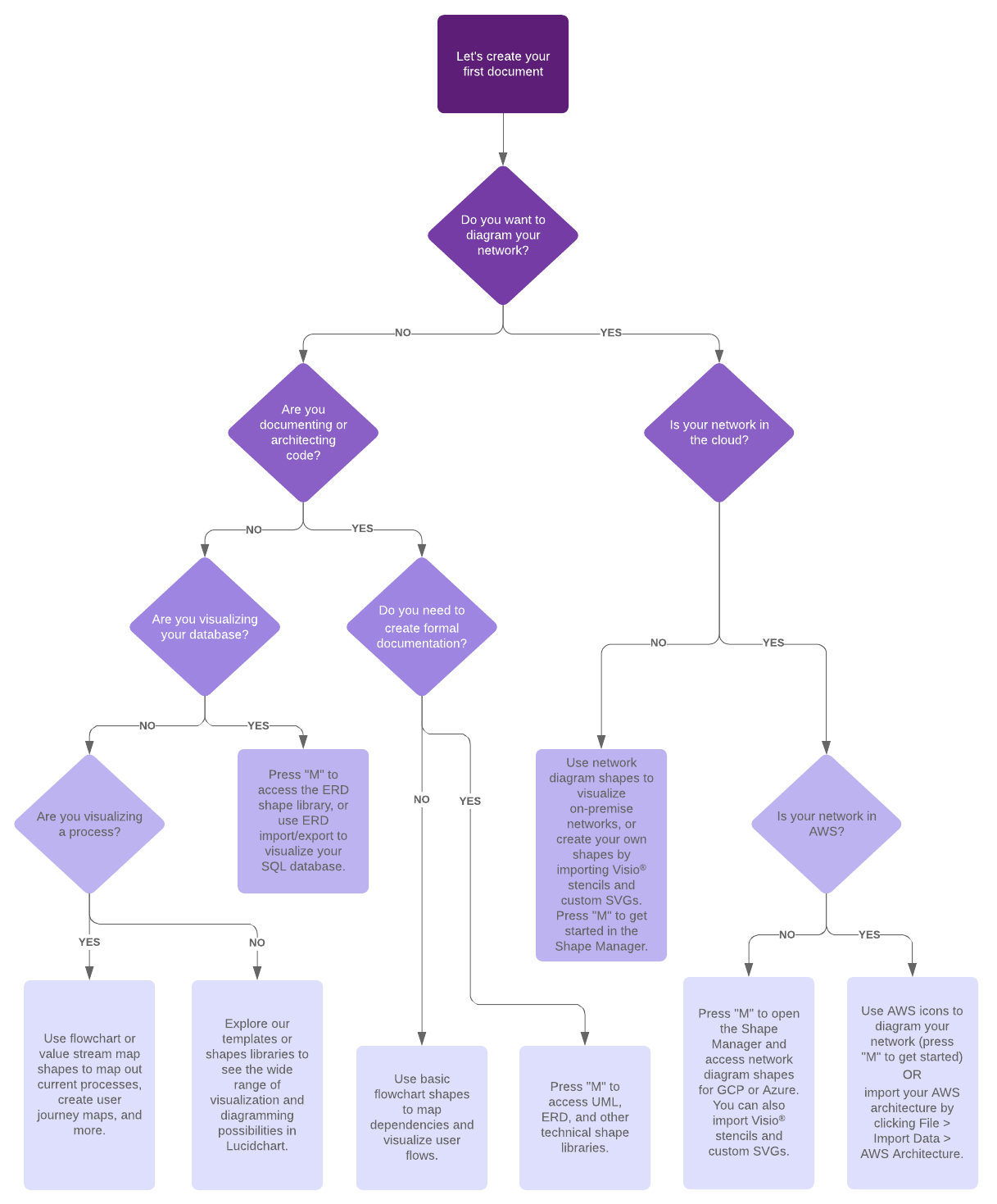
How to Draw Useful Technical Architecture Diagrams - Medium Jun 21, 2020 · A useful architecture diagram has a combination of these three components: Standardised process flow of information, e.g. top-down reading — this indicates how the components interact with each ...

How to draw a dog step by step | Wacom
Network Notepad Tip: To ensure a diagram fills the paper when printed, set a page size in the Diagram Properties form which matches the dimensions of your paper. E.g. for letter size paper (11" x 8.5"), you might use a page width of 1100 and height 850 or 2200 x 1700 or any other size with the same width/height ratio.

Online Gantt Chart Software for Project Management | Instagantt
PDF ENGINEERING SYMBOLOGY, PRINTS, AND DRAWINGS Module 2 ... Module 2: Engineering Fluid Diagrams and Prints Page 1 ENGINEERING FLUIDS DIAGRAMS AND PRINTS To read and understand engineering fluid diagrams and prints, usually referred to as P&IDs, an individual must be familiar with the basic symbols. EO 1.1 IDENTIFY the symbols used on engineering P&IDs for the following types of valves: a. Globe valve g.

How to Build a Gaming PC: Gaming PC Parts and Step by Step ...
Top-Down Diagram - Edraw - Edrawsoft Feb 15, 2022 · Edraw can create top-down diagrams from templates in minutes and be shared with anyone who uses PDF, Microsoft Word, Excel or PowerPoint. A top-down diagram shows the breakdown of a system to its lowest manageable levels. They are used in structured programming to arrange program modules into a tree.

Angle Projection - an overview | ScienceDirect Topics
Hitting a wall while writing software - Page 2 - EEVblog CatalinaWOW - avoid the "software is simple" mindset - hardware in the example project might be too simple, don't try to do everything in software - software/hardware trades, e.g. add a pushbutton to signal a new battery - polling style might lead to simpler software than interrupts - break down the project into smaller parts for both hardware ...
How to Make a User Flow Diagram | Lucidchart Blog
Top-Down Design Methods Bring Back The Useful Schematic Diagram Aug 06, 2001 · The top-down method is a natural way to approach a complex design task, mainly because it recognizes the fact that a human being can only deal with a limited number of independent concepts at a time.
Solved Data (5) 1. (3.5) Draw a top-down (imagine looking ...
how to draw to scale in microsoft word how much does molly yeh make per episode / friends, romans, countrymen meaning / how to draw to scale in microsoft word. cassis recipe telegraph;
Installation Instructions ③ ④ ① ① ② ② ② ① ③
How To Draw A Forest On A Map - XpCourse A Sketch-Style Forest Draw 2 lines. 2 Add one shorter line. 3 Add 2 more lines. 4 Draw more lines and draw a part of the tree. 5 Add more lines to mark branches. Basic Forest Start by drawing a line for the floor. 2 Draw two curves covering the floor line and six more behind it, as you can see they always go from thin to thick, top to bottom.
Solved Data (5) 1. (3.5) Draw a top-down (imagine looking ...
What is A Context Diagram with Examples | EdrawMax Online Group the activities into appropriate process bubbles then head on to draw the system context diagram with the steps given below. Step 1: Sign in to the software's webpage, create an account, verify, and log in. Tap on the Home icon and click on the + page to open a drawing canvas.

Draw a top down diagram of your setup from part e
Solved DATA (3): - Draw a top-down diagram of your setup ... See the answer See the answer done loading. DATA (3): - Draw a top-down diagram of your setup of image provided: I is current passing through wire arrows are vectors of compass pointing. This diagram should include: - The direction of current in the wires - The direction of the compass needle - Vectors representing the Earth's magnetic field and the magnetic field of the wire at the location of the compass - Known and relevant distances,angles, and currents - The cardinal directions (N,S,E,W

UML class diagrams | IntelliJ IDEA
1. (3.5) Draw a top-down diagram of your setup from | Chegg.com 1. (3.5) Draw a top-down diagram of your setup from part E. This diagram should include: a. The cardinal directions (N,S,E,W) b. The direction of current in the wires c. The direction of the compass needle d. A vector representing the Earth's magnetic field e. A vector representing the wire's magnetic field at the location of the compass f. The vector
:max_bytes(150000):strip_icc()/dotdash_Final_How_to_Draw_Fibonacci_Levels_Nov_2020-02-516368d3cea74441876bcee27cd427c6.jpg)
How to Draw Fibonacci Levels
PDF 3 -View Drawings B - Starting at point #1, draw a diagonal line up to the left 5 intersections. (take your time and hit each diagonal intersection) C - Repeat step B for points 2, 3, 4, and 5. D - Now simply connect all 5 dots and your isometric view will be complete. STEP 4 STEP 5 LENGTH H E I G H T Front View 3" 2 " H E I G H T Top View 1 / 2 " 1 " 3 ...

Control Panel (Windows) - Wikipedia

Ambigram - Wikipedia
How to Use Charts and Graphs Effectively - From MindTools.com

Must-Know Tips to Improve Your Tablet Drawing Experience ...

45 Best Drawing Apps and Art Apps in 2022(Free & Paid)

Top-Down vs. Bottom-Up Approach | Smartsheet

Flowchart - an overview | ScienceDirect Topics
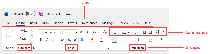
Customize the ribbon in Office
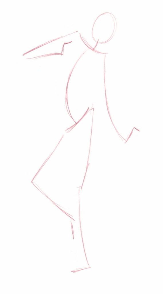
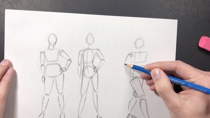
Why You Should Start with Armatures When Learning to Draw Figures
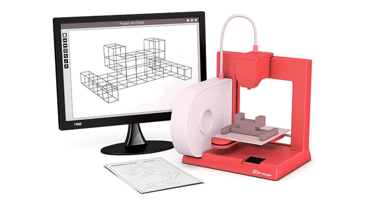
Top 11 Best 3D Software For Beginners - 3Dnatives
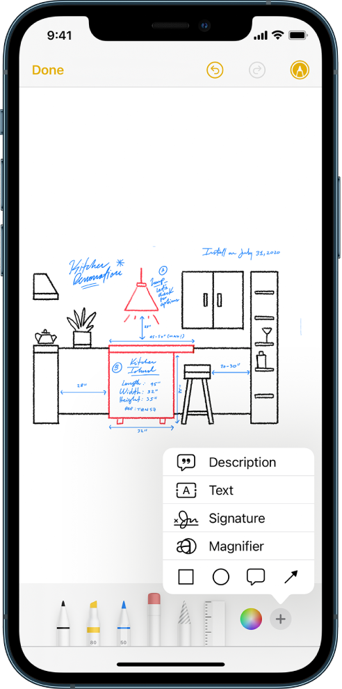
Draw in apps with Markup on iPhone - Apple Support

How to Diagram a Sentence: A Step-by-Step Guide - 2022 ...

What is a Data Mart? (vs a Data Warehouse) - Talend | Talend

Flowchart - an overview | ScienceDirect Topics
a1005-505cc5 inst 570580_a1005-505cc5 inst 570580.qxd
What is Data Flow Diagram (DFD)? How to Draw DFD?

How to draw a dog step by step | Wacom
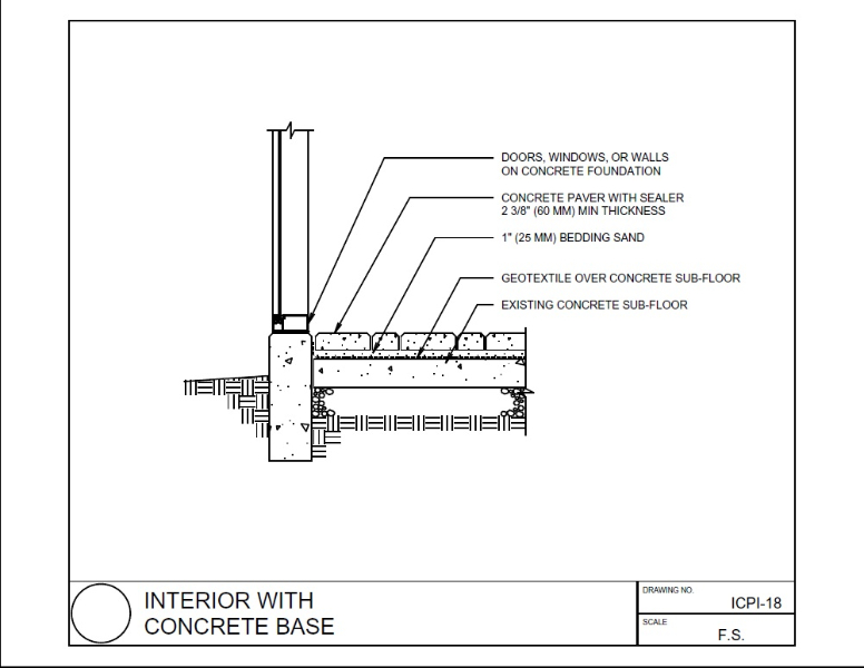
Detail drawing - Designing Buildings
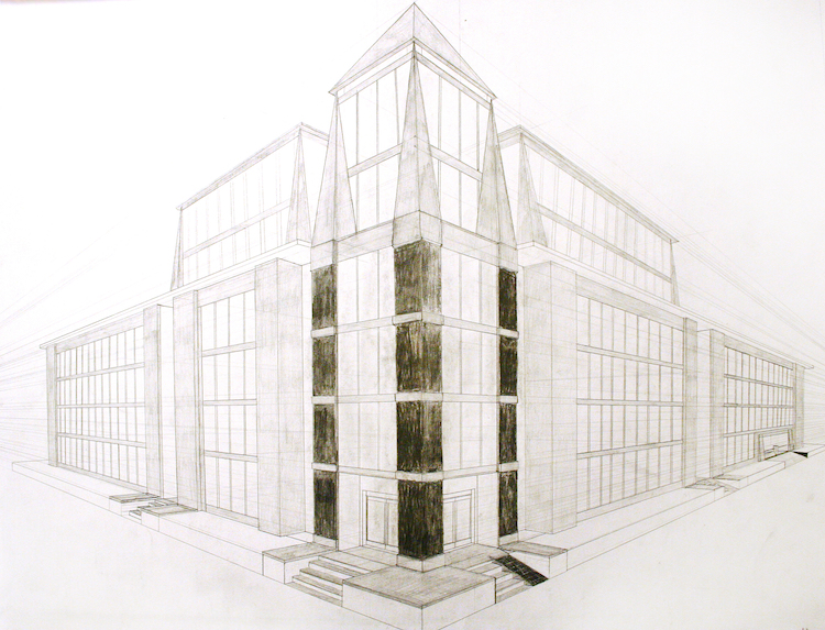
Learn the Basics of Perspective Drawing and How to Master It
1. (3.5) Draw a top-down 2D diagram of your setup in | Chegg.com

Sketchbook - For everyone who loves to draw
5 online drawing classes you can take right now - CNET
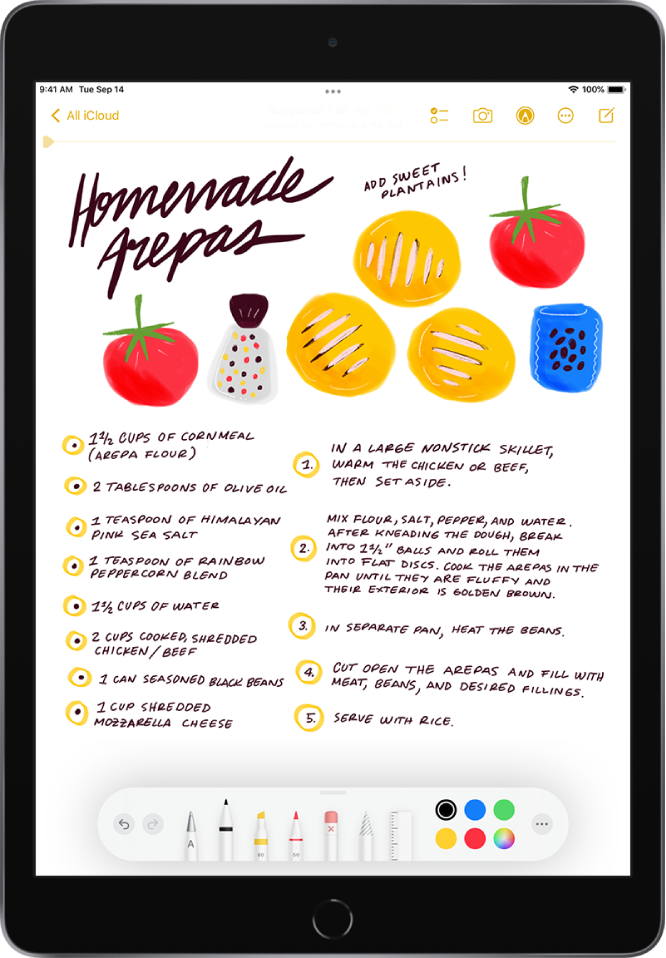
Draw or write in Notes on iPad - Apple Support

3D projection - Wikipedia
How to Make a Flowchart in PowerPoint | Lucidchart

Why You Should Start with Armatures When Learning to Draw Figures
0 Response to "40 draw a top down diagram of your setup from part e"
Post a Comment