41 phasor diagram rlc circuit
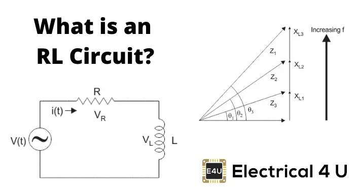
Series RLC Circuit — Collection of Solved Problems Series RLC Circuit. Task number: 1540. An AC circuit is composed of a serial connection of: a resistor with resistance 50 Ω, a coil with inductance 0.3 H. A phasor is an "arrow" that we use to plot the current and voltage values on individual components of the circuit into a phasor diagram. Phasor Diagram of Series RLC Circuit The NOTE: For remembering the phase relationship between voltage and current, learn this simple word called 'CIVIL', i.e in capacitor current leads voltage and voltage leads current in inductor. RLC circuit - For drawing the phasor diagram of series RLC circuit, follow these steps: Step - I...
PDF Natural and Step Response of Series & Parallel Natural Response of Parallel RLC Circuits. The problem - given initial energy stored in the inductor and/or capacitor, find v(t) for t ≥ 0. When the circuit's response is critically damped, the assumed form of the solution we have been using up until now does not provide enough unknown coefficients to...
Phasor diagram rlc circuit
RLC Series circuit, phasor diagram with solved problem RLC Series circuit contains a resistor, capacitor, and inductor in series combination across an alternating current source. The behavior of components can be explained by phasor diagrams, impedance and voltage triangles. PDF Section 9.12 Phasor Diagrams Example 9.6: Series RLC circuit (2). Thévenin equivalent circuit. response by using phasor and impedance? n What is the reflected impedance of a circuit with. Section 9.12 Phasor Diagrams. 54. Definition n Graphical representation of -7-j3 = 7.62Р-156.8° on the complex-number plane. impedance of RLC circuit from phasor | Electronics Forum... For example, I have a RLC series circuit like this: And here is the phasor diagram to calculate impedance of...
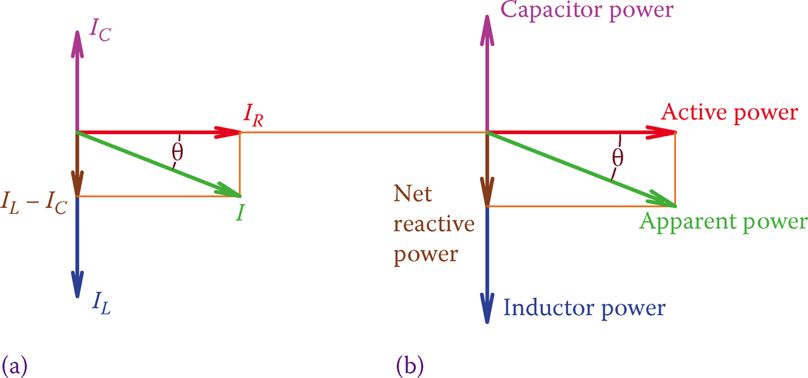
Phasor diagram rlc circuit. RLC Series AC Circuits | Physics Draw the circuit diagram for an RLC series circuit. Explain the significance of the resonant frequency. How does an RLC circuit behave as a function of the frequency of the driving voltage source? Combining Ohm's law, Irms = Vrms/Z, and the expression for impedance Z from [latex]Z... Phasor Diagram for a Parallel RLC Circuit Like the series RLC circuit, we can solve this circuit using the phasor or vector method but this time the vector diagram will have the voltage as its reference with the three current vectors plotted with respect to the voltage. The phasor diagram for a parallel RLC circuit is produced by combining... Series RLC Circuit (Circuit & Phasor Diagram) | Electrical4U The phasor diagram of series RLC circuit is drawn by combining the phasor diagram of resistor, inductor and capacitor. Before doing so, one should understand the relationship between voltage and current in case of resistor, capacitor and inductor. RLC circuit - Wikiversity A RLC circuit (also known as a resonant circuit, tuned circuit, or LCR circuit) is an electrical circuit consisting of a resistor (R), an inductor (L), and a capacitor (C), connected in series or in parallel. This configuration forms a harmonic oscillator. Tuned circuits have many applications particularly for...
Series RLC Circuit: Analysis and Example Problems Consider the circuit consisting of R, L and C connected in series across a supply voltage of V (RMS) volts. The resulting current I (RMS) is flowing in the circuit. For the convenience of the analysis, the current can be taken as reference phasor. Chapter 12.3 - Phasor Diagram of Series RLC Circuit | Engineering360 The nature of the phasor diagram of a series RLC circuit depends on the frequency f of the applied signal in relation to the frequency of resonance f0. Three different cases may be considered: (i) f = fr, (ii) f < fr, and (iii) f > fr. with f = f0, the reactance XL of inductor L equals the reactance of capacitor C. Phasor Diagram RLC Series AC Circuit | Physics Forums Engineering Parallel RLC circuit phasor diagram. Engineering AC Circuit Phasors. Engineering Electrical and Control Engineering: Transfer Function Reduction problem. What is RLC Series Circuit? - Phasor Diagram... - Circuit Globe The phasor diagram of the RLC series circuit when the circuit is acting as an inductive circuit that means (VL>VC) is shown below and if (VL< VC) the circuit will behave as Steps to draw the Phasor Diagram of the RLC Series Circuit. Take current I as the reference as shown in the figure above.
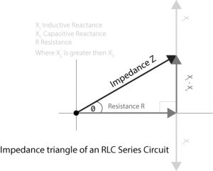
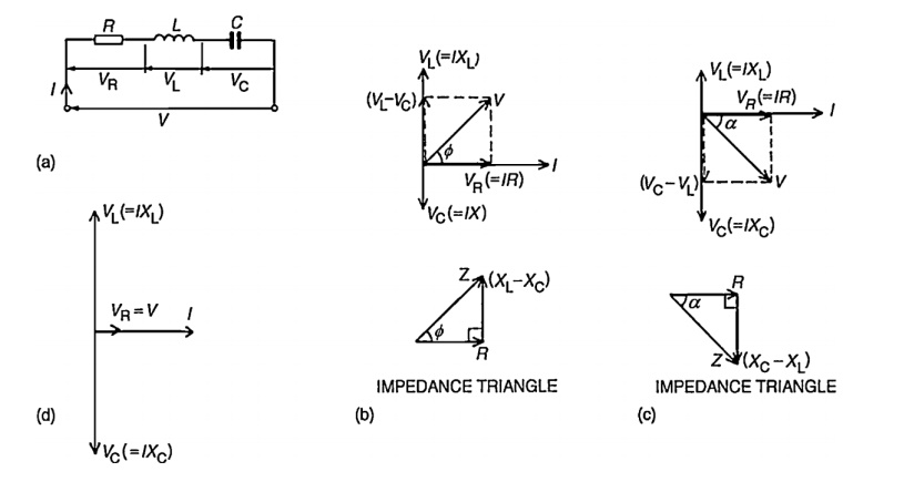
Series RLC Circuit | Analysis | Phasor Diagram | Impedance Triangle A series RLC circuit contains elements of resistance, inductance, and capacitance connected in series with an AC source, as shown in Figure 1. The three voltages of a series RLC circuit are combined, as shown in the circuit voltage vector (phasor) diagram of Figure 2 and constructed as follows Phasor Diagram of Series RLC Circuit - YouTube Phasor Diagram of Series RLC Circuit. Смотреть позже. passive networks - Phasor diagrams for RLC series circuit? How can I make phasor diagrams for the circuit in case when $$I_CI_L$$. The sign of the imaginary part will tell you if the circuit is predominantly inductive or predominantly capacitive . And hence if the current will lag the voltage or lead the voltage respectively. Phasor Diagrams | Brilliant Math & Science Wiki | Phasor of a circuit Phasor diagrams are a representation of an oscillating quantity as a vector rotating in phase space with an angular velocity equal to the angular frequency of the Phasor diagrams are used in simple harmonic motion and RLC circuits which have elements that are out of phase with one another and …
RLC Series circuit, phasor diagram with solved problem
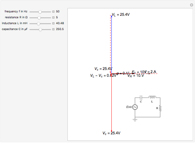
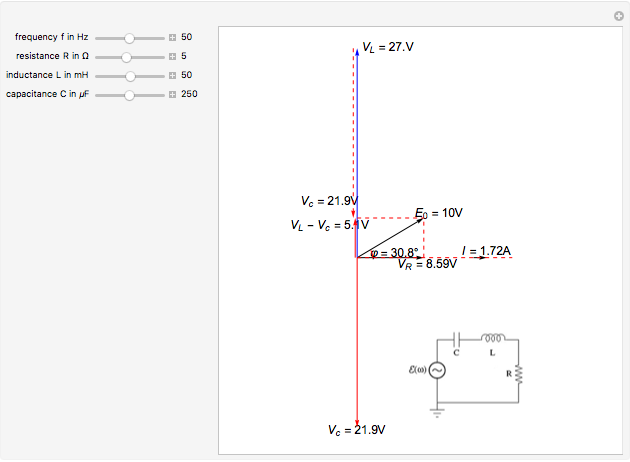
Phasor Diagram for Series RLC Circuits - Wolfram Demonstrations... This Demonstration shows a phasor diagram in an AC series RLC circuit. The circuit consists of a resistor with resistance , an inductor with inductance , and a capacitor with capacitance . The current in an RLC series circuit is determined by the differential equation.

RLC Series circuit, phasor diagram with solved problem
PDF RLC Circuits RLC Circuits. It doesn't matter how beautiful your theory is, it doesn't matter how smart you are. If it doesn't agree with experiment, it's wrong. Richard Feynman (1918-1988). OBJECTIVES To observe free and driven oscillations of an RLC circuit. THEORY. The circuit of interest is shown in Fig.

Phasor Diagram of RL, RC and RLC Circuits (with Examples)
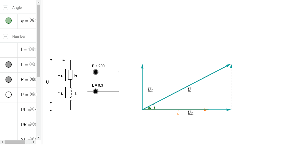
Driven RLC Circuit Using Phasors - GeoGebra This simulation shows the phasor representation of a series RLC circuit. Adjust the values of R, L, and C using the sliders. Change how the circuit is driven by adjusting the emf amplitude and driving frequency. Use the check boxes to select which graphs are shown.

EngineerMaths Power System Consulting: RLC parallel circuit ...
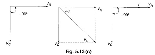
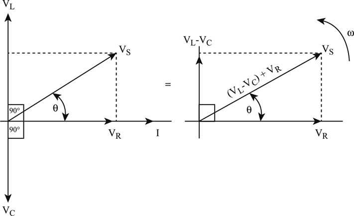
Phasor diagram for a series RLC circuit Drawing of the phasor diagram for a series RLC circuit energized by a sinusoidal voltage showing the relative position of current, component voltage and applied Consider a circuit in which R, L, and C are connected in series with each other across ac supply as shown in fig. The ac supply is given by

Phasor diagram - LCR circuit - For Xc greater than XL / Capacitive reactance greater than inductive
PDF EE101: RLC Circuits (with DC sources) M. B. Patil mbpatil@ee.iitb.ac.in . Department of Electrical Engineering Indian Institute of Technology Bombay. M. B. Patil, IIT Bombay. Series RLC circuit.

Figure 7.2 from Resonance and Impedance Matching 7.1 ...
Phasor Diagrams and Phasor Algebra - Electronics-Lab.com Phasor diagrams are very convenient when we need to add and subtract two signals that are not in fig 7: Differentiated and integrated phasors in a phase diagram. Consider an RC series circuit in which From this expression, we can represent the phasors of the RC circuit in a phase diagram in...

Phasor diagram of voltage versus current and relationship ...
Phasor diagrams and RLC curcuits | All About Circuits | Forum I've got a series RLC circuit where I've been asked to find the phase angle φ and the generator voltage. Date. Phasor diagrams RLC. General Science, Physics & Math. 0. Feb 12, 2020. M. Leading & Lagging Phasor Diagrams. Homework Help.

Phasor diagram - RLC series circuit
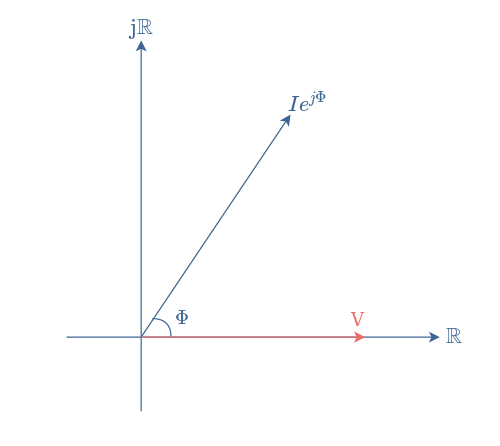
Phasor - Wikipedia An example of series RLC circuit and respective phasor diagram for a specific ω. The arrows in the upper diagram are phasors, drawn in a phasor diagram (complex (calculation) of the AC steady state of RLC circuits by solving simple algebraic equations (albeit with complex coefficients) in the...

Series RLC Circuit (Circuit & Phasor Diagram) | Electrical4U
RLC Series Circuit The RLC series circuit is a very important example of a resonant circuit. It has a minimum of impedance Z=R at the resonant frequency, and the phase angle is equal to The phasor diagram shown is at a frequency where the inductive reactance is greater than that of the capacitive reactance.

A driven RLC circuit is set up such that at its resonant ...
PDF RLC Circuits Lab: RLC Circuits. are the charge on the capacitor, the current in the circuit and the voltages across all the components. Damping is furnished by the resistor. 2.2.1 Explanation of phasor voltages. In AC circuits that have inductors and capacitors, voltage and current are not in phase with. one another.
Series RLC Circuit (Circuit & Phasor Diagram) | Electrical4U
Phasor Diagram - an overview | ScienceDirect Topics The purpose of a phasor diagram is to provide an efficient graphical way of representing the steady-state inter-relationship between quantities that vary Summarizing, when an RLC circuit is in a state of series resonance: • the circuit behaves as a pure resistance; • the inductive reactance is equal to...
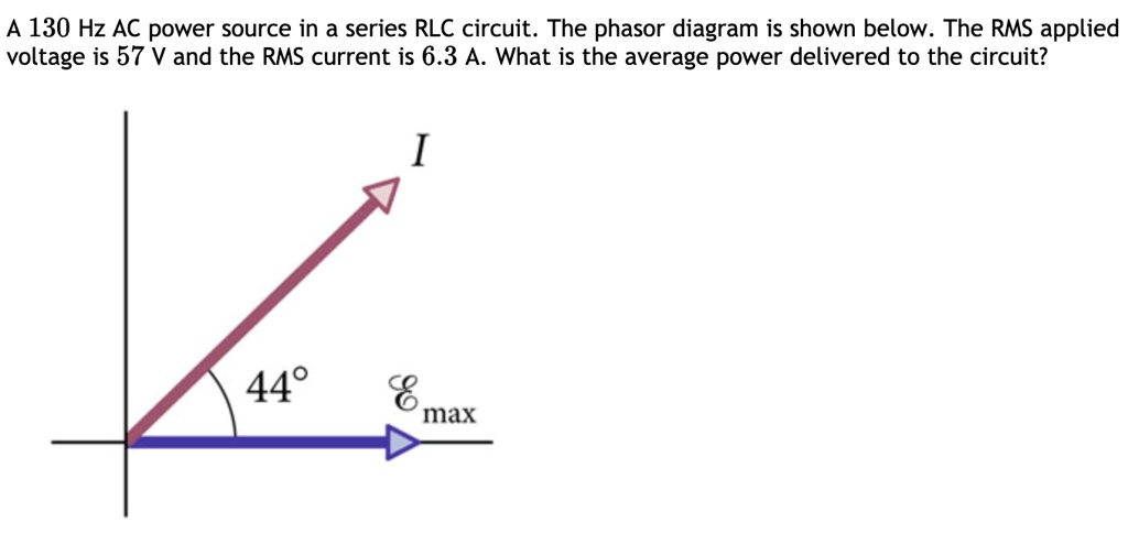
SOLVED:A 130 Hz AC power source in a series RLC circuit: The ...
Phasor Diagram for Series RLC Circuits This Demonstration shows a phasor diagram in an AC series RLC circuit. The circuit consists of a resistor with resistance. . The current in an RLC series circuit is determined by the differential equation.

Phasors and AC(sec. 31.1) Resistance and reactance(sec. 31.2 ...
impedance of RLC circuit from phasor | Electronics Forum... For example, I have a RLC series circuit like this: And here is the phasor diagram to calculate impedance of...
Phasor Diagram for Series RLC Circuits - Wolfram ...
PDF Section 9.12 Phasor Diagrams Example 9.6: Series RLC circuit (2). Thévenin equivalent circuit. response by using phasor and impedance? n What is the reflected impedance of a circuit with. Section 9.12 Phasor Diagrams. 54. Definition n Graphical representation of -7-j3 = 7.62Р-156.8° on the complex-number plane.
Series Circuit | Series RL Circuit | Series RC Circuit ...
RLC Series circuit, phasor diagram with solved problem RLC Series circuit contains a resistor, capacitor, and inductor in series combination across an alternating current source. The behavior of components can be explained by phasor diagrams, impedance and voltage triangles.

a) Series connection of L C circuit and (b) its phasor ...
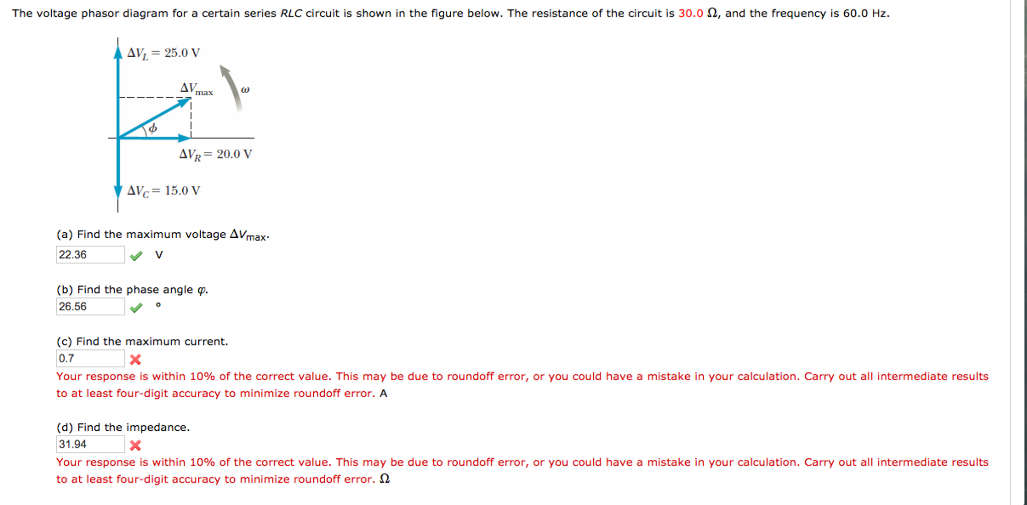
Solved The voltage phasor diagram for a certain series RLC ...
Parallel RLC Circuit — Collection of Solved Problems
Phasor Diagrams and Phasor Algebra - Electronics-Lab.com

Series RLC Circuit Impedance Calculator • Electrical, RF and ...

The phasor diagram for an RLC circuit is shown in the figure ...

Part 10: Further AC Theory | ITACA
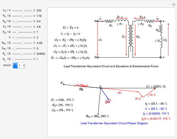
Circuit Phasor Diagram for Transformers - Wolfram ...
Phasor Diagram of RL, RC and RLC Circuits (with Examples)

Parallel RLC Circuit Impedance Calculator • Electrical, RF ...
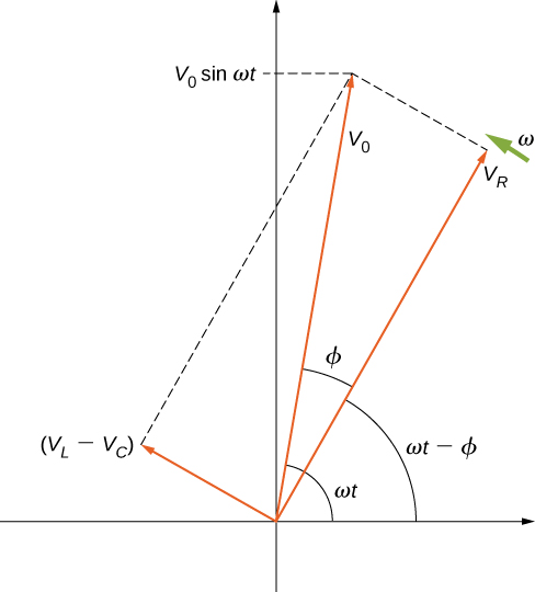
RLC Series Circuits with AC – University Physics Volume 2

Phasor - Wikipedia

Parallel RLC Circuit and RLC Parallel Circuit Analysis
Definition of The Series Rlc Circuit And Phasors | Chegg.com

RLC Series circuit, phasor diagram with solved problem
RL Series Circuit Analysis (Phasor Diagram, Examples ...
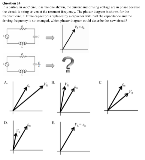
Solved Question 24 In a particular RLC circuit as the one ...

What are Series RLC Circuit and Parallel RLC Circuit?

Series RLC Circuit | Analysis | Phasor Diagram | Impedance ...
Phasor Diagram - RL Series Circuit – GeoGebra

Current and Voltages Computations in Series RLC circuit
Parallel RLC Circuit: Analysis & Example Problems ...
Phasor Diagram for Series RLC Circuits - Wolfram ...
Series RLC Circuit (Circuit & Phasor Diagram) | Electrical4U
Phasor diagram for a series RLC circuit
Get Answer) - 1. Figure shows the phasor diagram for an RLC ...
0 Response to "41 phasor diagram rlc circuit"
Post a Comment