38 motor control center wiring diagram
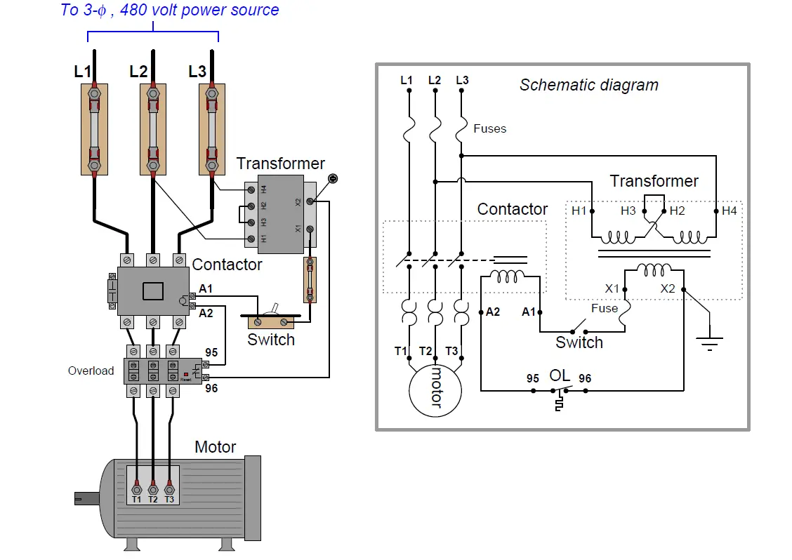
› worksheets › ac-motorAC Motor Control Circuits Worksheet - AC Electric Circuits A very common form of latch circuit is the simple “start-stop” relay circuit used for motor controls, whereby a pair of momentary-contact pushbutton switches control the operation of an electric motor. In this particular case, I show a low-voltage control circuit and a 3-phase, higher voltage motor: Low-voltage motor control centers documentation - Siemens USA Siemens motor control center wiring diagrams are at your fingertips within seconds. Use the tool below to quickly find and download one-line diagrams. E-House solutions - the fast-track project approach E-Houses are customized, pre-assembled, and pre-tested modular power substations. They are ideally suited for use in situations where fast ...
PDF GI-2.0: Typical Wiring Diagrams - Rockwell Automation Wiring diagrams or connection diagrams include all of the devices in the system and show their physical relation to each other. All poles, terminals, coils, etc. are shown in their proper place on each device. These diagrams are helpful in wiring-up systems, because
Motor control center wiring diagram
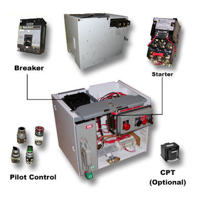
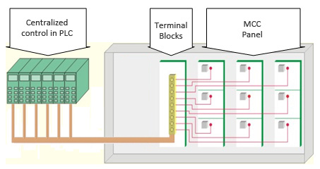
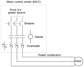
PDF Evolution Series E9000 Motor Control Centers imagination at work Evolution Series E9000™ Motor Control Centers Installation & Maintenance Guide DEH-40472 Rev. 06 GE Energy › blog › potentiometer-connectionPotentiometer Connection, Circuit Diagram, Wiring Guide | Linquip Jan 27, 2021 · 2. You should wire the center terminal to the output diagram on your instrument. Then, tin the other length of wire like the last section and join it with the center terminal on the POT. This terminal is the signal entering of the POT, so it requires to be covered properly in the instrument’s output. Mastering Motor Control Center (MCC): Wiring diagrams and ... Mastering Motor Control Center (MCC): Wiring diagrams and equipment from zero to hero An MCC comprises three buses for a three-phase system and the cabinet consists of a circuit breaker, a motor starter, and a control transformer; however, the actual contents vary widely as per requirements.
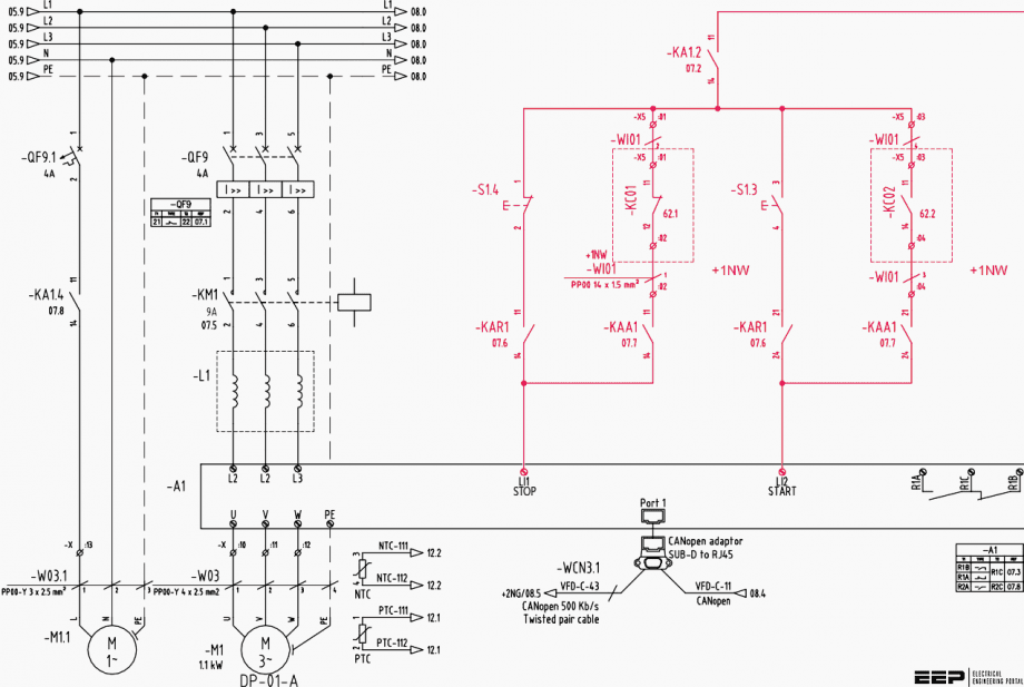
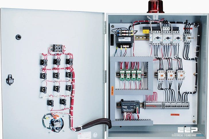
Motor control center wiring diagram. › kuphaldt › socraticAC motor control circuits - ibiblio wiring diagram calls for something different. It is your job to improvise a solution! file 00836 Question 4 Interpret this AC motor control circuit diagram, explaining the meaning of each symbol: L1 L2 Run M1 To 3-phase motor power source M1 Also, explain the operation of this motor control circuit. What happens when someone actuates the ... The Basics of Motor Control Centers (MCCs) | EEP Motor control centers are simply physical groupings of combination starters in one assembly. A combination starter is a single enclosure containing the motor starter, fuses or circuit breaker, and a device for disconnecting power. Other devices associated with the motor, such as pushbuttons and indicator lights may also be included. The wiring diagram and physical layout of the equipment ... The wiring diagram and physical layout of the equipment inside the motor control centre A front view with a closed door will also be given, so in that way, a detailed and comprehensive survey of an MCC will be achieved in both, functional and physical aspects. Example of MCC Motor Control Center Wiring Diagram | Electrical circuit ... Motor Control Center Wiring Diagram. Edgefx Kits. 11k followers . Types Of Electrical Wiring ... 60 Beautiful Motor Starter Wiring Diagram- Your starter went out and you desire to replace it: Here's what to do:First you dependence to acquire the obsolescent starter out. Sometimes it's simple and sometimes not. The single-handedly explanation it ...
42bots.com › tutorials › stepper-motor-wiring-how-toStepper motor wiring tutorial - 42 Bots Nov 22, 2014 · If no, then you are looking at a unipolar motor, where the two center tabs are connected. The cheap 28byj-48 stepper motor ( see tutorial ) is an example of that. You can still use the resistance test to determine the center tap, but the resistance between the other 4 wires will be the same, due to the common center tap. PDF CENTERLINE Motor Control Centers Installing A Centralized ... Installing the Wiring Diagram Holder 1. The centralized wiring diagram holder should be located on the inside of a bottom wireway cover, in any convenient section. Determine which section you want to locate the centralized wiring diagram holder. NOTE: If you motor control center has bottom fed incoming cables do not locate the centralized ... PDF 7700-Line Motor Control Center The 7700-Line motor control center, a quality product of the General Electric Company, has been designed and ... number which contains the wiring elementary diagram for this unit SIZE AMPS/HP The NEMA size rating of the starter. The ampere rating of the circuit breaker or fusible switch (for feeder PDF Basic Wiring for Motor Contol - Eaton Basic Wiring for Motor Contol Circuitry of a Starter Two-Wire Control Two-Wire Control circuits — or Low Voltage Release One of the common control wiring circuits used is known as Two-Wire or Low Voltage Release (LVR). It utilizes a main-tained contact type of pilot device — such as a thermostat, float switch or presence sensor. Figure 6
› wiring-diagramWiring Diagram – A Comprehensive Guide | EdrawMax Online Wiring Diagram, Pictorial Diagram, Layout Diagram, etc. Block Diagram, Logic Diagram, Single Line Diagram, etc. Most use for: A wiring diagram is mainly used in motor control installations and designing electrical circuits. Basic wiring for motor control - Technical data guide | EEP Wiring diagrams, sometimes called " main " or " construction " diagrams, show the actual connection points for the wires to the components and terminals of the controller. Basic wiring for motor control - Technical data They show the relative location of the components. They can be used as a guide when wiring the controller. PDF 2100-IN049B-EN-P, CENTERLINE® 2100 Motor Control Centers ... • CENTERLINE 2100 Low Voltage Motor Control Centers Instruction Manual, publication 2100-IN012, which is supplied with the MCC. • The unit wiring diagram supplied with the MCC unit. ATTENTION To prevent injury or death to personnel installing or servicing the switch, disconnect the motor control center remote power source(s) so that no Square D Mcc Bucket Wiring Diagram - schematron.org Siemens Motor Control Center wiring diagrams at your fingertips within seconds. Use our tool below to quickly find and download one line diagrams. To the top of the page. Download: Wiring Diagram Book - Square D Type NR Sockets,WELL-GUARD® Pump Panels,Definite Purpose Contactors ,Square D NEMA Relay. The Square D Model 5 motor control centers ...
The wiring diagram and physical layout of the equipment ...
Three Phase Motor Power & Control Wiring Diagrams Three Phase Motor Connection STAR/DELTA Without Timer - Power & Control Diagrams. Three Phase Motor Connection Star/Delta (Y-Δ) Reverse / Forward with - Timer Power & Control Diagram. Starting & Stopping of 3-Phase Motor from more than One Place Power & Control diagrams. Control 3-Phase Motor from more than Two buttons - Power & Control ...

MCC C CENTR | Instrumentation and Control Engineering
PDF MCC Ratings - EandM Class I, Type A Wiring Type A wiring is only available on Class I motor control centers. The motor control center manufacturer connects the combination motor control unit to the vertical bus via the stabs on the back of the unit. Power is applied to the circuit breaker from the vertical bus. The circuit breaker is factory wired to the motor ...

Star Delta Motor Starter Control Panel - Star Delta Motor ...
Motor Control Panel Wiring Diagram - U Wiring Motor Control Wiring Diagram Pdf wiring diagram is a simplified usual pictorial representation of an electrical circuit. Mastering motor control center mcc wiring diagrams and equipment from zero to hero an mcc comprises three buses for a three phase system and the cabinet consists of a circuit breaker a motor starter and a control.

MCC Electrical
Motor Control Center Explanation | MCC Panel wiring ... Motor Control Center Explanation | MCC Panel wiring diagram | MCC Panel | Control PanelHere in this video you will know about MCC or motor control center. Mo...

Motor Control Circuit Wiring - Inst Tools
› content › damMotor control centers— low voltage - Eaton The Freedom motor control center meets all the above listed standards, ratings and features. Freedom Arc-Resistant Eaton’s Freedom Arc-Resistant is the first motor control center to be tested to a North American guideline specifically written for low-voltage motor control centers, unlike C37.20.7 that is a guideline
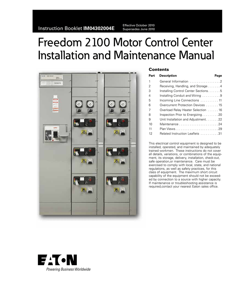
Freedom 2100 Motor Control Center Installation and Maintenance
PDF Installation manual - Freedom MCC - Eaton motor control center at the job site . General hints 1. Handle the motor control center with care to avoid damage to components and to the enclosure or its paint finish . 2. Keep the motor control center in an upright position . 3. Ensure that the moving means has the capacity to handle the weight of the motor control center . 4.

General Electric IC7700 size 1 Motor Control Center Bucket ...
en.wikipedia.org › wiki › Motor_controllerMotor controller - Wikipedia A motor controller is a device or group of devices that can coordinate in a predetermined manner the performance of an electric motor. A motor controller might include a manual or automatic means for starting and stopping the motor, selecting forward or reverse rotation, selecting and regulating the speed, regulating or limiting the torque, and protecting against overloads and electrical faults.

Motor Control Center Explanation | MCC Panel wiring diagram | MCC Panel Wiring
Mastering Motor Control Center (MCC): Wiring diagrams and ... Mastering Motor Control Center (MCC): Wiring diagrams and equipment from zero to hero An MCC comprises three buses for a three-phase system and the cabinet consists of a circuit breaker, a motor starter, and a control transformer; however, the actual contents vary widely as per requirements.
Basic wiring for motor control - Technical data guide | EEP
› blog › potentiometer-connectionPotentiometer Connection, Circuit Diagram, Wiring Guide | Linquip Jan 27, 2021 · 2. You should wire the center terminal to the output diagram on your instrument. Then, tin the other length of wire like the last section and join it with the center terminal on the POT. This terminal is the signal entering of the POT, so it requires to be covered properly in the instrument’s output.

Submersible pump Microcontroller Wiring diagram Three-phase ...
PDF Evolution Series E9000 Motor Control Centers imagination at work Evolution Series E9000™ Motor Control Centers Installation & Maintenance Guide DEH-40472 Rev. 06 GE Energy
Specialist Motor Control Centre And Motor Control Panel ...
Basic wiring for motor control - Technical data guide | EEP

GE 5 KV LimitAmp Motor Control Center with PowerVac Main ...
Buy Model 6 - Square D Motor Control Center
Underwriters Laboratories Label

Motor Control Center Explanation | MCC Panel wiring diagram ...

Circuit breaker Car Wiring diagram Electric motor Tachometer ...

Y-Δ transform Electric motor Wiring diagram Three-phase ...
MCC panel & smart MCCs - Electrical - Industrial Automation ...

Motor Control Center | Megawatt Power Limited

Square D Motor Starter Wiring Diagram | Magnetic motor, Solar ...

Evaluating advancements in motor control centres

File:Wiring diagram of motor control centre.JPG - Wikimedia ...

Motor Circuit Control Panel, Motor Protection Control Panel ...
Motor Control Circuit Wiring - Inst Tools

Motor Control Center Explanation | MCC Panel wiring diagram ...

AIM Manual - Page 56 | Single-Phase Motors and Controls ...
tiastar LV MCC catalog SGSA

DC VARIABLE SPEED MOTOR CONTROL

File:Wiring diagram of motor control centre on pump station ...

Sequence Controls for Motor Starters

Motor Control | Pro Circuit, Inc
AC Motor Control Circuits Worksheet - AC Electric Circuits

NEMA ICS 2.3 1995 Instruction for Handling, Installation ...

Square D Model 6 Motor Control Center 2 HP
Mastering Motor Control Center (MCC): Wiring diagrams and ...

Motor control center - Wikipedia

Motor Control Center Design Guide 600V | PAKTECHPOINT
0 Response to "38 motor control center wiring diagram"
Post a Comment