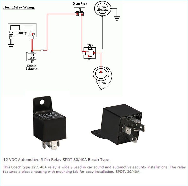
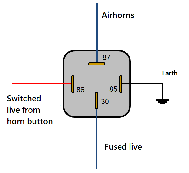
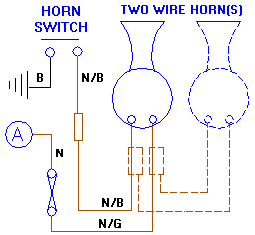
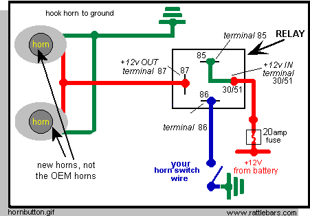
38 push button horn wiring diagram
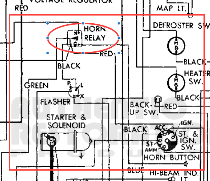
PDF Electrical system | wiring diagram reference chart Wiring Diagram - HLC -. Horn, cigarette lighter and clock. sequence (A to I) is activated by press the either reset buttons. NOTE: If either reset button is not pressed for 20 seconds at each step or if the ignition switch is turned OFF, the self-diagnosis mode is exited. Horn Wiring - JeepForum.com When you push the horn button it grounds the relay. If you want to narrow your search, try grounding the relay directly. My diagrams say that wire goes from your power distribution box to the bulkhead connector through the loom along the top of the firewall.
Horn wiring - Ford Truck Enthusiasts Forums Not much in Shop manual wiring diagram or pages #276-77-78 regarding horns Photo of horn via ebay 1950 FORD F -1 FLATHEAD V-8 6 VOLT HORN: eBay When I used 12AWG wire to push just two of my horns - at 12 volts! - that wire was not big enough to carry the power necessary to blow the horns (remember at...

Push button horn wiring diagram
1965 and 1966 Mustang horn wiring and troubleshooting The first diagram is the 64 1/2 horns, which have a horn relay and only one wire for a contact in the turn signal switch. In this picture of the back of the three-legged horn button I have circled two contacts on it. When you push on the horn button, that causes one, or both, of the contacts on the... PDF UltraShift DM3 6-Speed Wiring Diagram with Push Button Shifter UltraShift 10-Speed Wiring Diagram with Analog Shifter. Horns & Wiring Diagram - YouTube Horns & Wiring Diagram. Смотреть позже.
Push button horn wiring diagram. Push Button Horn Wiring Diagram - Automotive Diagram Images Diagram Push Button Station Wiring Diagram Full Version Hd. Index Of Wp Content Uploads 2018 02. Horn Problem Morris Minor Owners Club. 1959 Chevy Apache Headlight Wiring Diagram Wiring Diagram. Sho Me 100 Watt Full Feature Siren Model No 30 2100. Push Button Horn Wiring Diagram For Your Needs Read wiring diagrams from unfavorable to positive and redraw the signal being a straight range. All circuits are usually the same - voltage, ground, single component, and changes. Push Button Horn Wiring Diagram Source: a-dingli.tripod.com. Any diagram or picture showing how to install a horn button? | Forum Also looking for the wiring diagram of this car. Take the horn button, and making sure it's aligned in the center of the steering wheel Push slightly against the retaining clip and push the bottom part into... OMP Push Horn Wiring | ClioSport.net OMP Push Horn Wiring. Thread starter pastymaster. Start date Mar 2, 2017. The OMP wheel should have come with a red and black wire with spaded ends to just hook them up from OE wiring to the back of the horn button, if not maplin sell them for pence.
This is a how-to:Nrg short hub install with proper horn wiring... | Forum The horn wire is the green wire with the red stripe. I just used a vampire clip to connect to it The problem comes when you push the horn button in to the spacer and the spacer turns out to not be deep enough so the triangle spring in the button get... Automotive Horns | GTSparkplugs | Horn Wiring Examples Horn Wiring Examples. Wiring up horns are pretty easy since your car likely has one already. Some cars have simple wiring that does not use a relay Or decided to wire up something this way for some reason maybe via a push button switch. In any case this is what the other typical wiring for you... Horn Wiring | IH8MUD Forum Horn Wiring. Thread starter Boaf 32. These pics show my dilemma...horn buttons terminate at wheel center but I don't see how this hooks up to harness wiring...any help is greatly appreciated. a little off-topic, there's a wiring diagram above with some colored lines. How did someone do that? SOLVED: How can I fix the horn button on the steering wheel? - iFixit Push wires through the access holes and remove horn switch. (7) To install, reverse the previous procedures. Use caution not to pinch wires. Here's a link to the wiring diagram section of the repair manual which includes the horns. Here's an image taken from the wiring diagrams showing the...
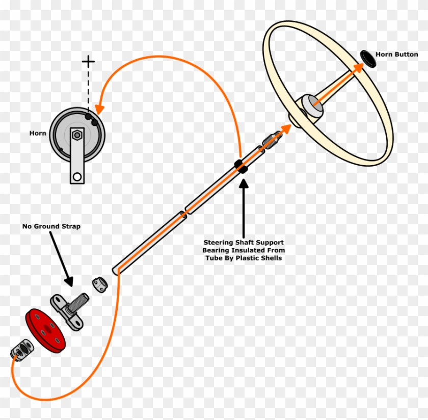
Peugeot all models wiring diagrams - general 11 - reading wiring diagrams: N: harness identification. O: fuse box diagram. 1041: emergency stop switch. 1042: general relay. 1043: re-setting push button. 2501: horn button in steering wheel. 2505: air horn compressor relay. Horn Wiring Battery grounded, hot wire to push button, push button to horn, then ground horn. It would be nice if it could be that simple, but it is not. For the years after '59, we'll identify the "potential", or voltage state, of several steering column points for each setup using the diagram above. Electrical wiring diagram WIRING DIAGRAM. Provides circuit diagrams showing the circuit connections. The ground points circuit diagram shows the connections from all major parts to the respective ground points. DIODE A semiconductor which allows current flow in only one direction. HORN An electric device which sounds... How To Wire A Car Horn To A Push Button - AISARANGHEO Wire Horn Diagram Wiring. Ferrari 137819 Electric Horn Push Button Scuderia Car Parts. Buy Motorcycle Auto Horn Push Button Resettable Switch Green Red. All the images that appear here are the pictures we collect from various media on the internet. If there is a pictures that violates the rules...
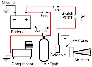
air horn wiring | The Diesel Stop looking to wire up my compressor & horns... I would like to use my upfitter #1 to turn on my compressor and charge my tank.... but I would also like air horn wiring. Jump to Latest Follow. When the relay is closed, 12v should flow through the relay to the factory horn, grounded when the wheel is pushed.
Push Button Horn Wiring Diagram - Free Catalogs A to Z Category: Universal horn button wiring diagram Show details. 800-2.0 Typical Wiring Diagrams for Push Button Control. 6 hours ago Typical Wiring Diagrams For Push Button Control Stations 3 Genera/ Information @ Each circuit is illustrated with a control circuit (continued) schematic or line...
Horn wiring diagram? | Toyota Sienna Forum - siennachat.com Horn wiring diagram? Jump to Latest Follow. I can toggle between them or use both with the original horn button as well as the panic button. Still kinda confused as to why they used separate circuits for the snail horns and the disc horn.
Subaru Crosstrek Service Manual - Wiring system Horn system Wiring diagram. Immobilizer system Wiring diagram. Instrument panel wiring harness Location. Push button start system Wiring diagram.
how to wire a push button horn - Create Web Buttons No Coding... · Push button Horn Wiring Diagram - wiring diagram is a simplified adequate pictorial representation of an electrical circuit. 1. two lengths of wire 2. a 12v push button switch 3. a charged 12v battery One section of wire to any part of the horn(ground) to the -(negative) of a 12v battery. the other...
Re-wiring Horn w/ Button - MustangForums.com This is the S197's horn wiring diagram. Any help is appreciated. Or feel free to call me an idiot, question why I'm doing this, etc. I don't know offhand what color the code "DB" refers to (for the wire running into pin 7 from pin 39 of the SJB).
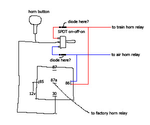
Horn Wiring Help Needed (switch between two horns) | Tacoma World Installed an air horn and want to install a SPDT switch to toggle between the stock horn and the new air This is so I can use the steering wheel horn button to control each set of horns separately. You need to get a manual that has the wiring diagram for your truck. Then follow the color-coded...
PDF Wiring Diagram Book WIRING DIAGRAM A wiring diagram shows, as closely as possible, the actual location of all component parts of the device. When the Jog push button is pressed, the starter coil is energized (independent of the relay) and no holding circuit forms, thus jogging can be obtained.
Push button Horn Wiring Diagram | autocardesign A wiring diagram is often used to troubleshoot problems and to create positive that all the connections have been made and that anything is present. push button horn wiring diagram electrick wiring diagram co. Architectural wiring diagrams operate the approximate locations and interconnections...
PDF SERVICE | Forum IMPORTANT: Warning Horn Requirement - The remote control or key switch assembly must be wired with a warning horn. a - Trigger b - Stator c - Temperature Switch d - Warning Horn e - Push-Button Stop Switch 90-852572R1 JANUARY 1998. c d e f.
Air Horn wiring and troubleshooting booklet | Manualzz AIR HORN BASIC OPERATION PRINCIPLES AND ELECTRICAL WIRING DIAGRAM The motorcycles stock horn draws only a small amount of power In the wiring diagram shown when the horn button is pushed power flows through terminals 85 & 86, this activates a small electromagnet inside the relay.
Puch Moped Horn Wiring Diagram (Chrome Oval Switches) | PDF How does the horn button play into the circuit? Since the Blue w/Black wire going to the horn is already energized, the horn button will actually When the button is pushed, the engine doesn't die because it is now finding it's ground path through the horn (think light filament again) (see diagram)...
Horns & Wiring Diagram - YouTube Horns & Wiring Diagram. Смотреть позже.
PDF UltraShift DM3 6-Speed Wiring Diagram with Push Button Shifter UltraShift 10-Speed Wiring Diagram with Analog Shifter.
1965 and 1966 Mustang horn wiring and troubleshooting The first diagram is the 64 1/2 horns, which have a horn relay and only one wire for a contact in the turn signal switch. In this picture of the back of the three-legged horn button I have circled two contacts on it. When you push on the horn button, that causes one, or both, of the contacts on the...











0 Response to "38 push button horn wiring diagram"
Post a Comment