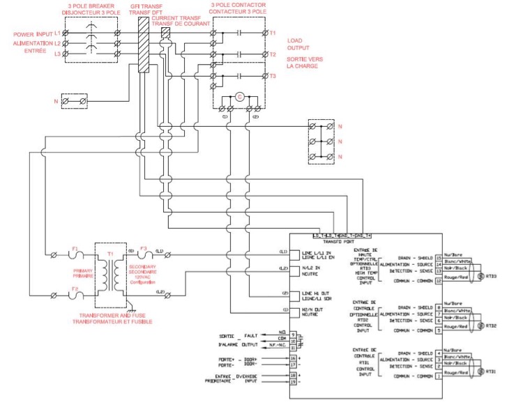
39 heat trace wiring diagram
PDF Electric Heat Tracing - Thermon isometric system diagrams (if provided). • Lay out the trace heater on the pipe, at the 4 or 8 o'clock position (Illustration B), securing it tightly against the pipe with attachment tape. Wrap bands of tape around the trace heater and pipe at intervals of 12" (30 cm) or less, keeping the trace heater in close contact with the pipe. Installation, Operation and Maintenance Manual for The ... 2.2 General Wiring Details To connect heaters, power and signals it is necessary to remove the clear cover of the enclosure remove the brass thumb knob to allow the hinged plate to be raised. Incoming power supply is connected to the terminal block in the lower left corner of the enclosure with ground connected to the ground bar.
Heat Trace Wiring Diagram Gallery - Wiring Collection heat trace wiring diagram - A Newbie s Overview of Circuit Diagrams An initial take a look at a circuit representation might be confusing, but if you could check out a subway map, you can review schematics. The function is the exact same: obtaining from factor A to direct B. Literally, a circuit is the path that enables electricity to circulation.

Heat trace wiring diagram
PDF Chromalox Three Phase Equations and Heater Wiring Diagrams Typical Heater Wiring Diagrams The following diagrams show typical heater wiring schematics. Single Phase AC circuits where line voltage and current do not exceed thermostat rating. Three Phase AC heater circuit where line voltage and current do not exceed thermostat rating. Circuit does not have a "positive" off. Heat Trace Wiring Diagram - Free Wiring Diagram Heat Trace Wiring Diagram. Assortment of heat trace wiring diagram. A wiring diagram is a simplified standard photographic depiction of an electrical circuit. It shows the elements of the circuit as simplified forms, as well as the power as well as signal links in between the devices. A wiring diagram normally offers info concerning… Raychem Heat Trace Wiring Diagram instructions that are included in this manual and product packages must heat- tracing systems. 1. Colder As with any electrical equipment or wiring installation operating at .. D Raychem heating cable can be cut-to-length without affect-.Typical Installation Details.
Heat trace wiring diagram. Heat Trace Type CM-1 Microprocessor Based Heater Cable ... Nelson™ Heat Trace CM-1 microprocessor based heater cable monitoring system continually monitors the status of both series and parallel styles of electric heat tracing cables and panels. The CM-1 monitors the supply voltage and current flow to each heating device. With the addition of continuity monitoring devices (CMD), this system monitors ... Chromalox Installation Manuals U Series Long Line Heat Trace Connection Kits. Unitary Immersion Heaters. RSTO RSTO-B Installation Manual PN400 Washdown and Corrosion Resistant Unit Heater Accessories. HD3D - HD3DS ... IntelliTrace Modbus Wiring & Registry Map Instructions PDF Design Guide and Installation Details for ... - Heat Trace The following step-by-step procedures will enable you to determine the length of heating cable required to efficiently heat trace pipes, valves and flanges. Alternate Voltages RSCC 240 VAC self-regulatingheating cables can be operated at alternative voltages. The chart below compares heating cable power output with prod- uct rating. 920 Series, Controller Assembly - Heat Trace | nVent 920 Series, Controller Assembly. nVent RAYCHEM Controller assembly for the nVent RAYCHEM 920 series, which is a compact, full featured, microprocessor based, single-point heat-tracing control and monitoring systems for freeze protection and temperature maintenance. Thanks for your submission. A customer service agent will be in touch soon to ...
240 Volt Electric Heater Wiring Diagram - U Wiring This diagram from the Baseboard Owners Guide shows how to you can wire multiple heaters to one thermostat if youre using volt. PDF 3M Self-Regulating Heat Tracing Cables Self-Regulating Heat Tracing Cables for Commercial Buildings PLEASE NOTE: The diagrams and instructions outlined in this guide are for illustration purposes only. They are not necessarily to scale and do not necessarily represent exact real-world heat tracing systems. In addition, they are not meant PDF DigiTrace 910 Series Heat Trace Controller The 910 Series electronic Heat Tracing Controller controls, monitors, and communicates alarms and data for one heating circuit. The ability to install the units in Class 1, Division 2 areas supports PDF Design, Installation and Maintenance Manual - Heat Trace Maintenance of electric heat tracing systems shall conform to all IEC requirements for the use of electrical equipment and with the requirements of the relevant heat tracing standard, usually either IEC 62395 Electrical resistance trace heating systems for industrial and commercial applications or IEC 60079-30 Explosive atmospheres - electrical
Special Installation Instructions Supplement Duct-o-bar ... provided Heat Trace Wiring diagram. • Power must stay on to the Heater Control Panel for system to work properly. Power should be brought to Heater Control Panel from separate disconnect. • Heater Control Panel wiring diagrams and external heater cable circuit wiring diagrams are provided with the system. PDF Heat Trace Tube Bundle Installation - Mustang Sampling Drill holes and secure the heat shrink boots. 3. Bring in the Heat Trace Tube Bundle into the P53 Sample Conditioning System. 4. Open the controller cover and safely leave the wires hanging. 5. Switch the multimeter to Volt AC and safely apply power to the P53 Sample Conditioning System. 6. Put the black lead on the chassis ground. PDF Tracemate-277v voltage range of the heat trace cable. Wiring methods must conform to Class 1, Division II or Class 1, Zone II requirements. Heater Wiring Connect heatingcable wiring toterminals3 and 4.See Figure 2.2. If the heating cable has a braid, it should be terminatedtothe ground studusing a ring terminal suitable for #10 stud. Figure 2.3 GroundConnection How to Install Heat Trace - Powerblanket Begin attaching the heat tracing cable to the pipe on the lower half of the pipe at a 45° angle (looking at the pipe straight on, attach a single cable at 4 o'clock and if using an additional cable, at 8 o'clock). Attach the cable using heat or fiberglass tape every 6" to 1' back toward the power source.

Pipeline Skin Electric Current Tracing Cable
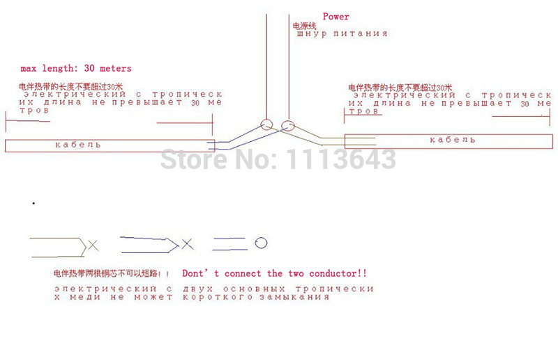
Heat Trace and GFCI, GFEP | Mike Holt's Forum Nov 19, 2010. #1. I have a situation where I have outdoor heat trace cables (2 @ approx. 100' @ 5w/ft.) that I would like to design to plug into outdoor receptacles (on the same circuit). I realize that by NEC code, I should put the circuit on a GFEP type breaker. My question is if I should utilize a GFCI receptacle for the outdoor location.

Process Electric Heat Tracing System | PAKTECHPOINT
Heat Trace Wiring Diagram Sample - Wiring Diagram Sample heat trace wiring diagram - What's Wiring Diagram? A wiring diagram is a kind of schematic which uses abstract pictorial symbols to show each of the interconnections of components in a system. Wiring diagrams comprise a couple of things: symbols that represent the components inside circuit, and lines that represent the connections together.
Wiring Diagram
PDF NELSON HEAT TRACE - Emerson Electric The Nelson Heat Trace CM-2201 is designed to monitor and controloneheating circuitinordinaryandClassI,Division 2, ClassI,Zone2,andZone2 hazardous locations. The CM-2202 can monitor/control two heating circuits in those same locations.

Heat Tracing In Piping: Types, Working, Use, Installation ...
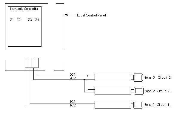
Wiring Diagram - Urecon Electric Heat tracing on Plastic Pipes Types of Cable Urecon Constant Watt Thermocable® Typical Thermocable® Installation Accessories for Thermocable® Series Type Self-Regulating Electronic Controllers NGUTC-2030 and NGUTC-2230 Thermostats Specifications Three-Phase Contactor Thermostat Program Codes Wiring Diagram
Intech 21, Inc. Design Guide 1
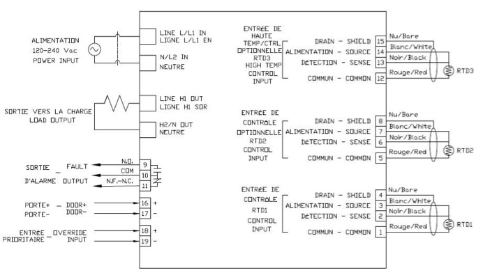
PDF TraceNetTM Control and Monitoring System TCM2 - Thermon RTD field wiring should be shielded and the shield grounded at one end. Ground connections are provided in the panel for this purpose. HEATER CT1, 2 and 3: In normal 2 circuit configuration, HEATER CT1 is used for Circuit 1, HEATER CT2 is used for Circuit 2 and HEATER CT3 is not used.
Nelson CLT28 Heat Tracing Cable - Modular Connection ...
Heat Tracing - Urecon In most cases, a THERMOCABLE® heat tracing cable is pulled into trace conduits in long circuit lengths, after the pipes have been field assembled. These trace conduits are factory applied to the pipes prior to insulating and are tested to ensure that no foam has entered into the conduits during the foaming process.
Pressure Transmitters Heat trace impulse lines ...
PDF Nelson Heat Tracing Systems Specification / Application ... DESCRIPTION These thermostats are used for controlling heat tracing systems in ordinary locations. The capillary bulb should be mounted on the side of the pipe. ENCLOSURE Molded Fiberglass Polyester CLASSIFICATIONS NEMA Type 4X IP66 TEMPERATURE RANGE Fixed Range 4.4°C (40°F) CAPILLARY Length Material Max. Bulb Temp. 0.9m (3ft.)
Intech 21, Inc. - HCCM-2100 Heater Cable Control and ...
Chromalox Heater Wiring Diagram Heat Trace Skid Systems · ITAS-EXT Installation Manual. Chromalox Technical Documents Technical Technical Information Three Phase Equations & Heater Wiring Diagrams Typical Heater Wiring Diagrams Three. Phone: wiringall.com 1. Wire all heaters and controls in accordance with the appropri- ate wiring diagram provided below.

Process Electric Heat Tracing System | PAKTECHPOINT
PDF C910-485 Heat Trace Controller - nVent The following drawings provide sample wiring diagrams for the C910-485 control products and optional accessories. Refer to Figure 2.2 for wiring terminal locations. Please contact your local nVent representative for information regarding other available options. Figure 2.2 -Power Connection 2.5.1 Power Connections

FIGURE B6.11 Components and electrical flow in skin effect ...
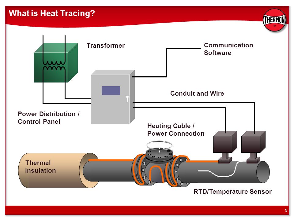
PDF Heat Trace Design Guide - ARCO Engineering Electric heat tracing systems are designed to make up for the heat lost from process system equipment through the thermal insulation. In some cases, the heat tracing system can be used for system heat-up at initial startup or after a power shutdown. The information in this design guide will allow the

Chromalox Installation, Operation Industrial Heating Cable ...
Raychem Heat Trace Wiring Diagram instructions that are included in this manual and product packages must heat- tracing systems. 1. Colder As with any electrical equipment or wiring installation operating at .. D Raychem heating cable can be cut-to-length without affect-.Typical Installation Details.

Frost Protection Cables | Eltherm ELP/SI-F Heater Cable ...
Heat Trace Wiring Diagram - Free Wiring Diagram Heat Trace Wiring Diagram. Assortment of heat trace wiring diagram. A wiring diagram is a simplified standard photographic depiction of an electrical circuit. It shows the elements of the circuit as simplified forms, as well as the power as well as signal links in between the devices. A wiring diagram normally offers info concerning…
Thermostat and Timers for Heat-Trace
PDF Chromalox Three Phase Equations and Heater Wiring Diagrams Typical Heater Wiring Diagrams The following diagrams show typical heater wiring schematics. Single Phase AC circuits where line voltage and current do not exceed thermostat rating. Three Phase AC heater circuit where line voltage and current do not exceed thermostat rating. Circuit does not have a "positive" off.

Skin Effect Heat Tracing

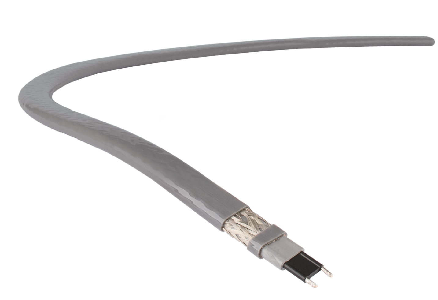
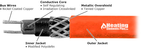
Heat Tracing Cable Cross Section - Heating and Process
STAR Park Forum September Who We Are Through its global ...
FLX - Verwarmingsoplossingen voor processen

How Does Self Regulating Heat Cable Work?

Self Regulating Cable Construction – Mineral Insulated Cable ...
Heat Tracing
Self-Regulating Heat Trace Cable - Medium Temp
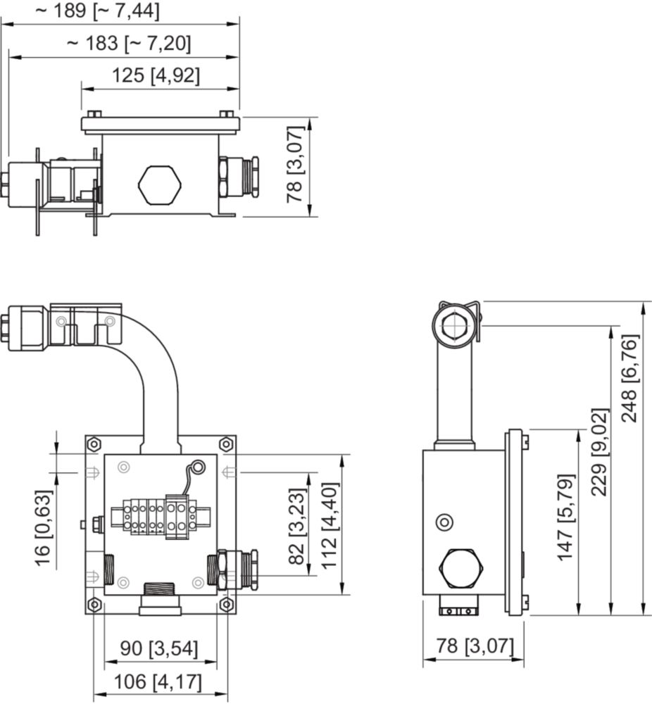
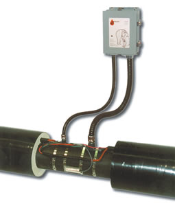
Junction box for heat tracing For pipe mounting - 259479
Installation and Maintenance Manual: GA-2129, CM-1 Heat Trace ...
Valin Snow Melt Catalog Master
Wiring Diagram

How to Select, Install, Operate and Maintain Electric Heat ...

HTSX Heat Tracing Cable | Frost Protection Water Pipes
Heating technology Electric Tracing leader-

465 Electronic Controller for Heat Tracing of Fire Protection ...

Electrical Heat Tracing Control & Monitoring Basics - ppt ...

Recommended spare capacity above the expected load for the ...

Heat Trace Control Diagram .dwg -CAD blocks free

Raychem Single Pipe Grease And Oil Line Maintenance Solutions ...

The Ives Equipment Process Engineering & Control Blog: Basics ...
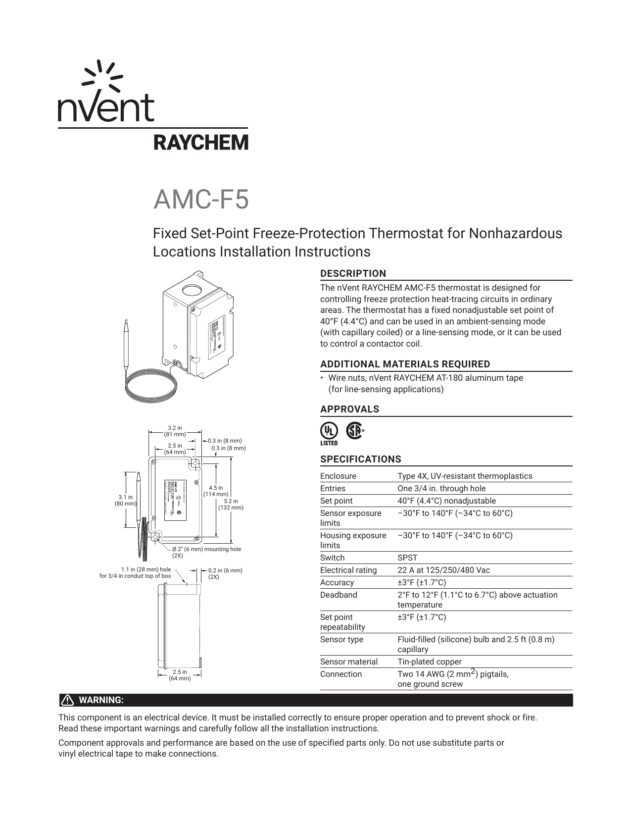
Raychem AMC-F5 Installation Manual | Manualzz

2300 Series Self Regulating Heating Cable - Leominster, MA
2M 12V Self Regulating Heat Trace Cable for Freeze Protection ...

The Quintessential Guide: Troubleshooting Electrical Heat ...
![Exhibitor] Yingfan Thermal Control Technology (Shanghai) Co ...](http://www.coatexpo.cn/uploadfiles/image/20210819/16293576075591016.jpg)
Exhibitor] Yingfan Thermal Control Technology (Shanghai) Co ...
0 Response to "39 heat trace wiring diagram"
Post a Comment