42 autometer fuel level gauge wiring diagram
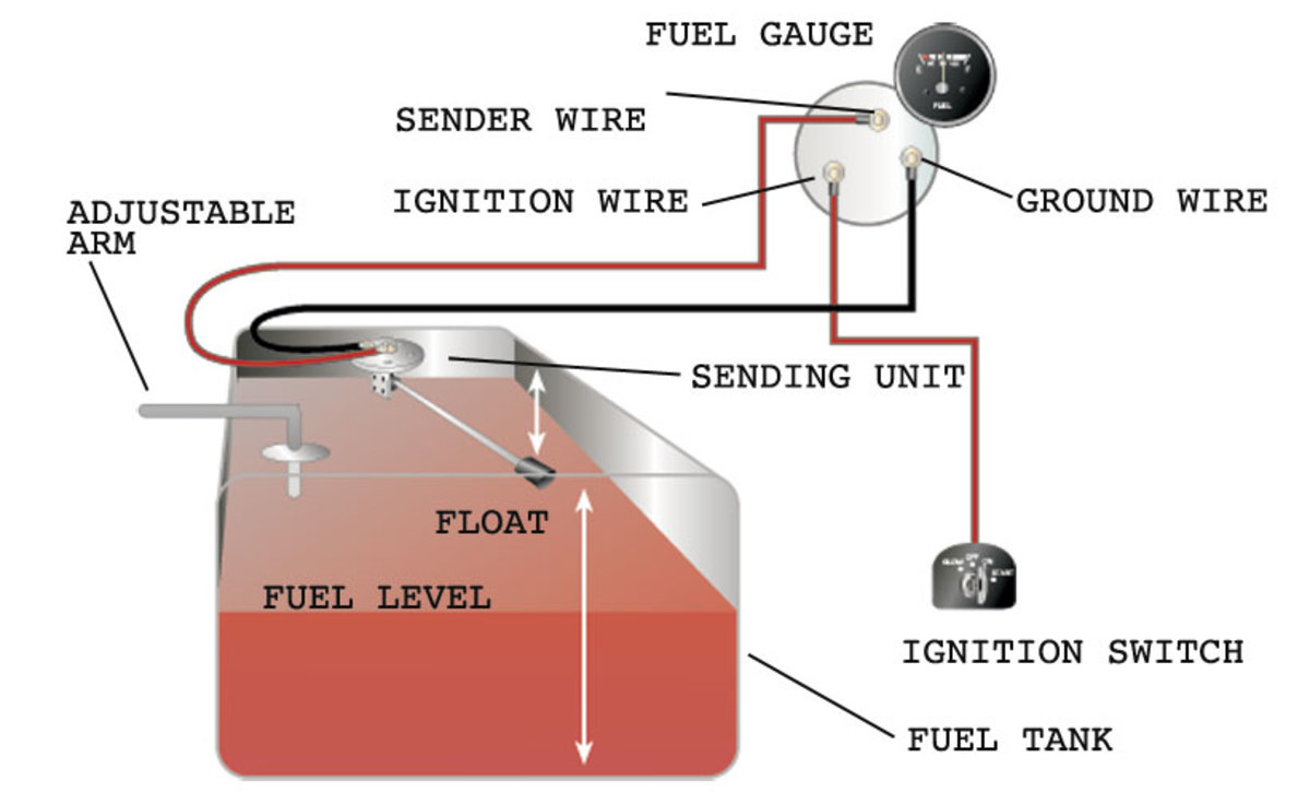
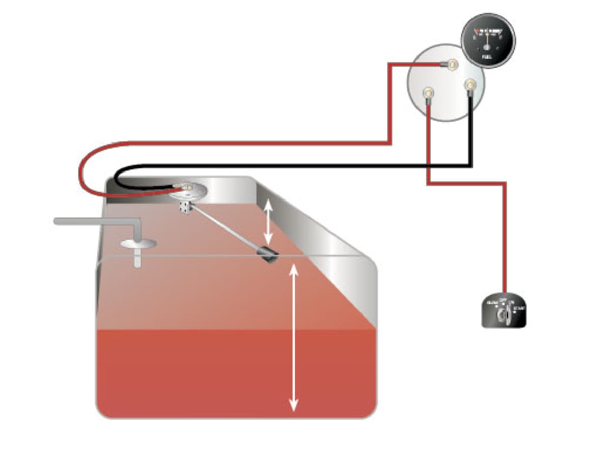
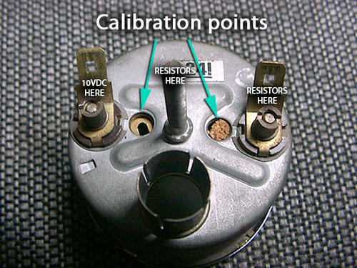
AutoMeter gauges, Fuel Level, Painless Wiring - Hot Rod Forum Starting with the lowest value (30 Ohm) put each resistor on the Sender line to ground..Keep going until you find the resistance value that "Just Pegs" the meter out..That's your system resistance..Say 90 ohms..Then you order a fuel sender for 90 ohms from the distributer..that should set it right.. Of Course , there is option 2..: {NOT ADVISED} PDF Installation Instructions Short Sweep Electric Fuel Level ... SHORT SWEEP ELECTRIC FUEL LEVEL GAUGE 2650-1858-77 Wiring: Sending Unit Wiring: Gauge Mounting: Gauge to Sender Compatibility: Looking at the rear of the gauge, you will have 3 terminals labeled S, I, & GND. You may use 18g or 20g stranded wire for all fuel level gauge wiring. S = This connects to the sending unit in the fuel tank. **(See ...
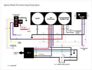
Autometer Gauge Wiring Diagram Short Sweep INSTALLATION INSTRUCTIONS. SHORT SWEEP ELECTRIC FUEL LEVEL GAUGE. Wiring: Sending Unit Wiring: Gauge Mounting: Gauge to . Replace your missing coolant temp sending unit in your Auto Meter gauge today This is the correct water temp sending unit for use with all Autometer Short Sweep Electrical Water Temp gauges. A graph showing this site's ...

Autometer fuel level gauge wiring diagram
Autometer Gauge Wiring Diagram - easywiring Sep 10, 2021 · Wiring diagram for auto meter new wiring diagram auto gauge a newbie s overview of circuit diagrams. Toll free tech support. Pin On Gauges Higginbotham fuel gauge wiring diagram rate fuel gauge wiring autometer gauge wiring diagram additionally wiring diagram provides you with enough time frame by which the assignments are to be accomplished. Autometer … PDF Installation Instructions Short Sweep Electric Gauges Fuel Level 1. Gauge connects to fuel sender on fuel tank. Existing wires may be used, or route proper length of 18 gage, wire from fuel tank to gauge. If a new hole is drilled in the firewall a grommet is recommended. Connect one end to terminal post on fuel level sender and the opposite end to the sender (S) terminal spade on back of gauge. 2. PDF Auto Meter Gauges Installation Instructions - CARiD.com Fuel Level. 1. Gauge connects to fuel sender on fuel tank. Existing wires may be used, or route proper length of 18 gage, wire from fuel tank to gauge. If a new hole is drilled in the firewall a grommet is recommended. Connect one end to terminal post on fuel level sender and the opposite end to the sender (S) terminal spade on back of gauge. 2.
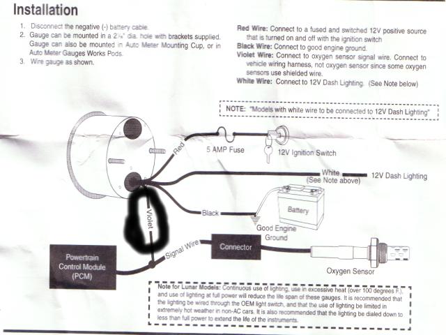
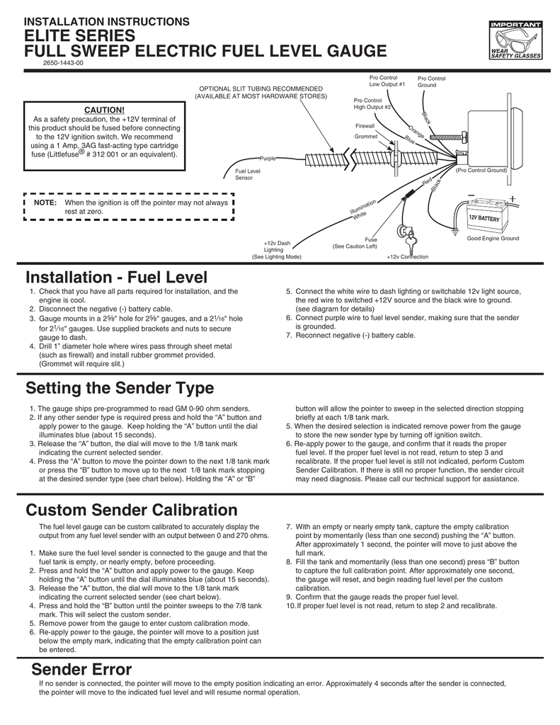
Autometer fuel level gauge wiring diagram. DIGITAL FUEL LEVEL - Autometer Existing wires may be used, or route the purple sender wire to the fuel tank. (The stock fuel level gauge, if equipped, must be disconnected.). Autometer Voltmeter Wiring Diagram - easywiring Voltmeter instructions wire nut flat washer nut washer voltmeter grommet u bracket do not leave any hardware out of these connections diagram 1 ground source step 2 should be connected as shown in diagram 1 to the voltmeter s connection post marked. 1 16 diameter gauges mount in 2. Step 6 connect positive wire. Fuel Level Gauges Autometer How They Work How To Install ... Fuel Level Gauges Autometer How They Work How To Install Tutorial Instructions Ohms Wiringhttp:// -----... PDF Installation Instructions Full Sweep Electric Fuel Level 4. Connect the purple sender wire to the fuel level sender. Existing wires may be used, or route the purple sender wire to the fuel tank. (The stock fuel level gauge, if equipped, must be disconnected.) 5. Connect the white wire to dash lighting or switchable 12v light source. 6. Connect one of the black wires to a good ground.
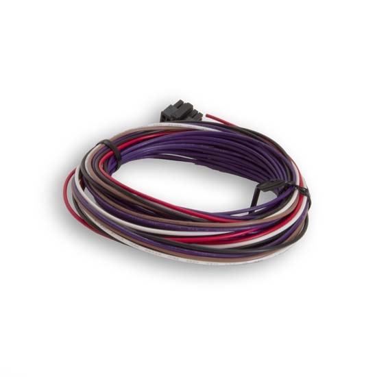
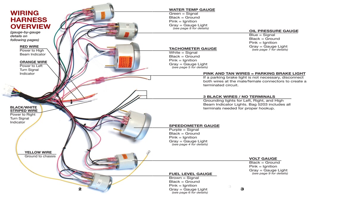
Programmable fuel level harness wire identification and ... - Autometer wiring diagram. (viewed from the wire in side of the plug). 1. Purple - Fuel level sugnal from sender. 2. Brown - Used to program custom fuel level. How to Wire Auto Meter Fuel Gauges - It Still Runs Identify and isolate the four wires protruding from the back of the gauge pod. These will be labeled "S" for the fuel-sender signal wire, "+" for the 12V positive wire, "-" for the 12V negative wire and the last will be the gauge-light power wire. Step 2 Connect the end of the "-" wire to a bare-metal surface on the vehicle. Autometer Electric Fuel Pressure Gauge Wiring Diagram ... Autometer electric fuel pressure gauge wiring diagram. Connect the purple sender wire to the fuel level sender. Universal gauge wire harness for installing auto meter electric speedometer tachometer and short sweep electric oil pressure water temperature fuel level and volt meter gauges. Autometer fuel level gauge trouble - Chevy Nova Forum Autometer fuel level gauge trouble. Jump to Latest Follow 1 - 11 of 11 Posts. numbersguy · Registered. Joined Jul 6, 2006 · 423 Posts . Discussion Starter · #1 · Feb 24, 2020 (Edited) I knew the sender was wonky, got a little bent putting it in years ago so when it was full it would read well past and bounce a bit but it settle down to an ...
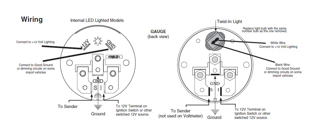
fuel Level Custom Sender Calibration Setting the ... - Autometer (see diagram for details). 6. Connect purple wire to fuel level sender, making sure that the sender is grounded. 7. Reconnect negative (-) battery cable. Resources - Autometer Auto Meter Products. 413 W Elm St. Sycamore, IL 60178. Toll Free Tech Support: 866.248.6357. Toll Free Customer Service: 866.248.6356. International: 815.895.8141 Autometer Water Temp Gauge Wiring Fuel level. 1. Gauge connects to fuel sender on fuel tank. GAUGE (back view) Wiring Ground Note: Sender grounds through threads Black Wire: Connect to Good Ground or dimming circuits on some import vehicles GND S I Pressure Gauges Temperature Gauges TEMPERATURE SENDER USE TEFLON SEALING COMPOUND ON PIPE 1. Install temperature sender. Fuel Gauge wiring question? | Team Camaro Tech I've replaced all my factory gauges in my '68 with Autometer stuff and am having problems getting the fuel gauge to work. Originally, the car came with the in-dash fuel level gauge. My wiring diagram shows 1 tan wire running to the fuel gauge. However, there are two tan wires at the back of the plug which ran into the pod/circuit board.
2-1/16
FULL SWEEP ELECTRIC FUEL LEVEL - Autometer Existing wires may be used, or route the purple sender wire to the fuel tank. (The stock fuel level gauge, if equipped, must be disconnected.).
How To Diagnose a Fuel Gauge Easy Not in the Book Tricks!
Faria Gauges Wiring Diagram - schematron.org Connect the blue lighting wire to one of the other blue lighting wires on a nearby gauge. Faria wiring diagram along with vdo gauges wiring diagrams gooddy together with mercruiser tilt and trim gauge wiring diagram as well as faria tachometer in addition omc trim gauge wiring diagram together with document as well as autometer fuel level gauge ...

Auto Meter Sport-Comp 2-1/16" Fuel Level Gauge, Programmable ...
PDF Fuel Level Sender Installation Instructions - vdo-gauges.com wiring instructions. Always disconnect battery ground before making any electrical connections. Parts of the Fuel Level Sender Unit to be Ad Fuel Level Sender Installation: Refer to the VDO catalog for matching fuel gauges. The unit can be adjusted to read accurately in tanks from 6" to 23" deep. Diagram B I. Measure the depth of your fuel tank.

Fuel Level Sender Installation Instructions - VDO Gauges ...
Auto Meter Electronic Speedometer Wiring Diagram - easywiring Auto meter electronic speedometer wiring diagram. Recommended auto meter hall effect sender 3 wire 16 pulses revolution. Hole in the firewall for the speedometer wires. See speedo senders below for available auto meter senders the speedometer should be calibrated to ensure accurate operation after installation. Secure wiring diagram 1 w typical.
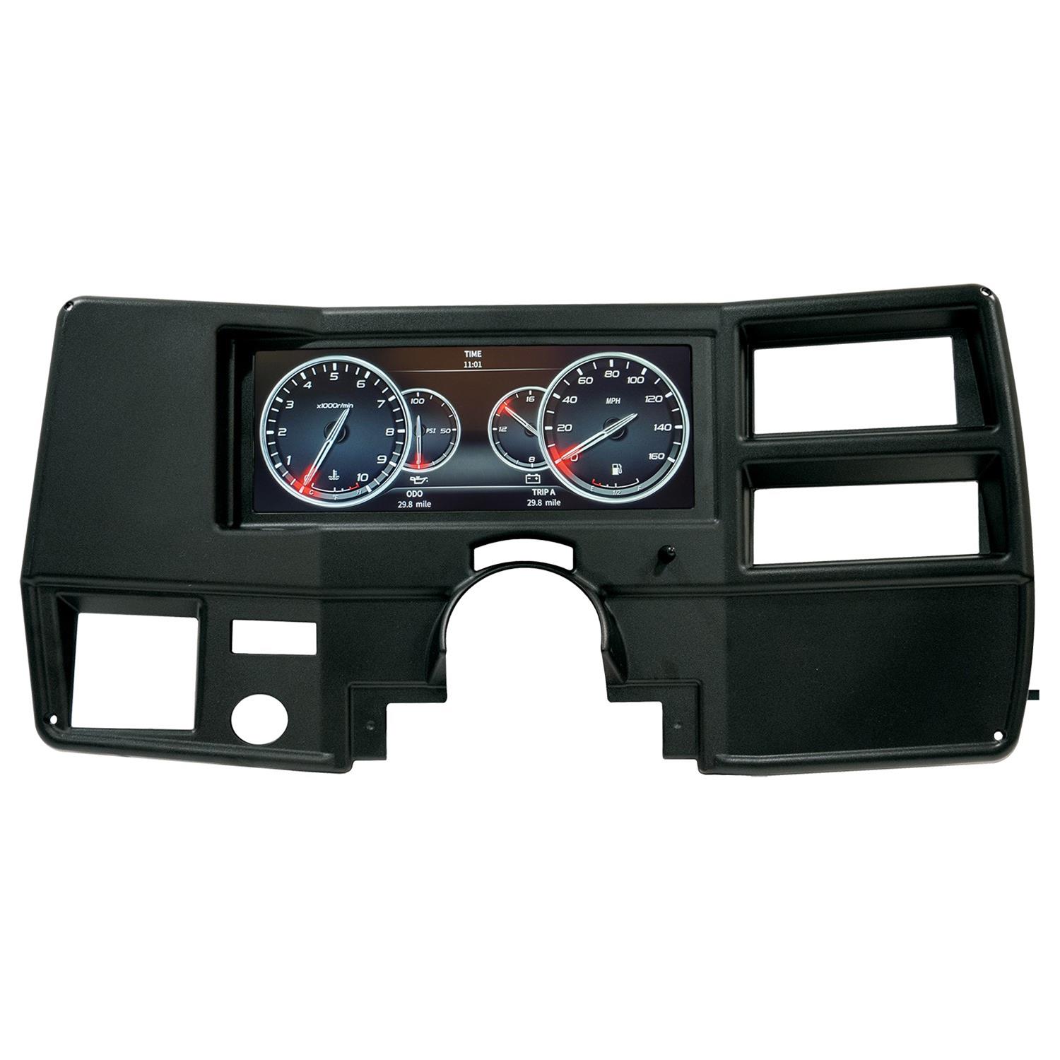
How to Install Auto Meter Direct Fit Dash Gauge Panel (97-06 ...
Autometer Trans Temp Gauge Wiring Diagram Just follow the diagram on the back of the gauge, and we'll help with the. INSTALLATION INSTRUCTIONS. DIGITAL TEMPERATURE GAUGES. cartridge fuse (Littlefuse® # or an equivalent). Installation. WIRING. HARNESS (see diagram for details) Digital display will dim B. Trans . Autometer Egt Wiring Diagram
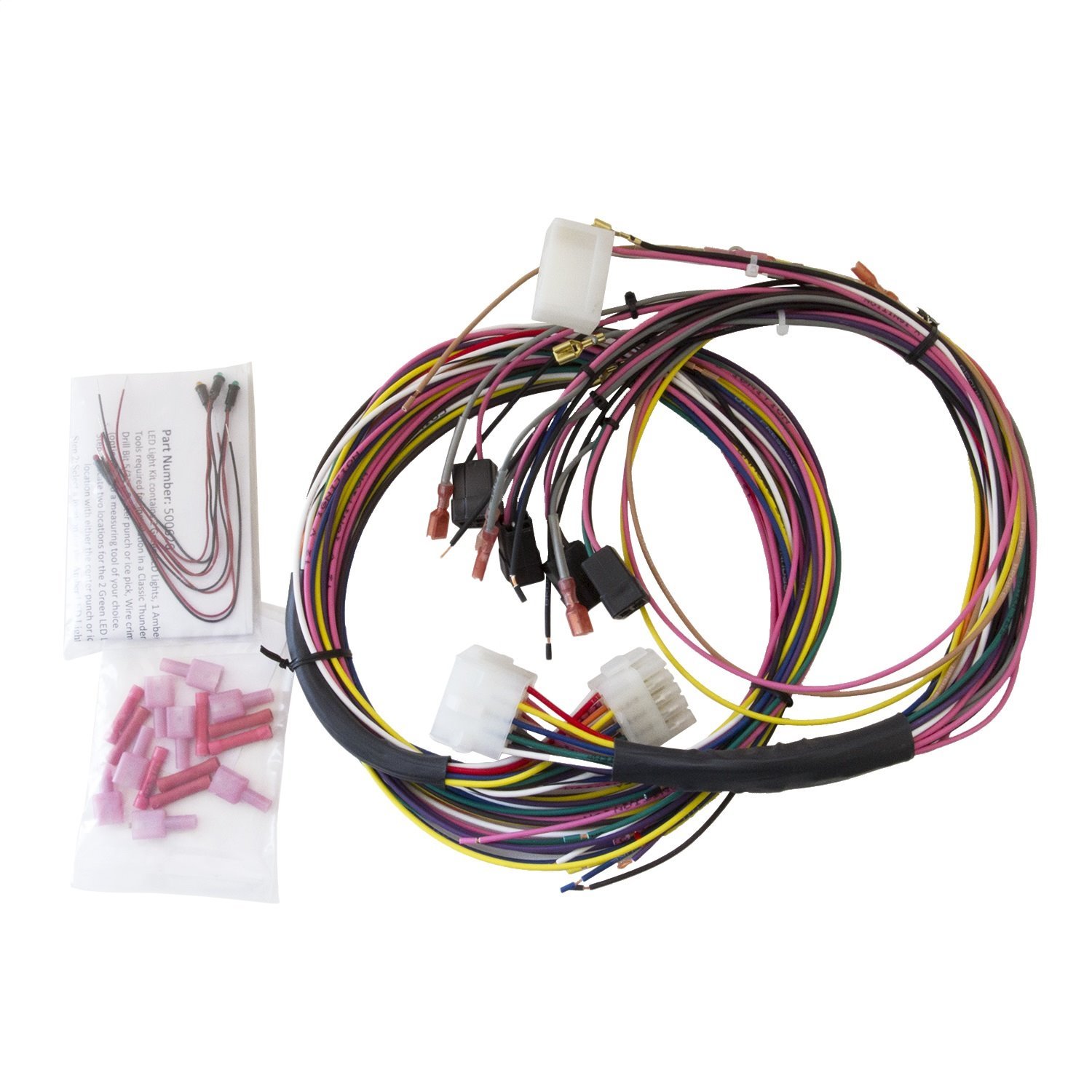
Auto Meter Replacement Wiring Harness Universal
A little bit of help with Wiring Autometer Gauges ... I have all my gauges mounted in the cluster and I have a few q's. I am trying to make sense of this Wiring Diagram 1. For the fuel level gauge, is the ground that goes to the stock fuel gauge, which also appears to be coming through the voltage regulator grounded to the tank, or is this...
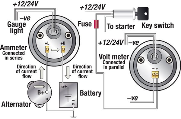
Troubleshooting Boat Gauges, Instruments and Meters | BoatUS
Equus Tachometer Wiring Diagram NOTE: To install the light bulbs, use needle nose pliers to insert the bulb in the bulb receptacle on back of gauge, then twist clockwise ¼ turn to lock into place.Lost the wiring diagram for my equus tach,, its - FixyaEquus Tachometer Wiring Diagram. Diagram. Auto Wiring Diagram

1
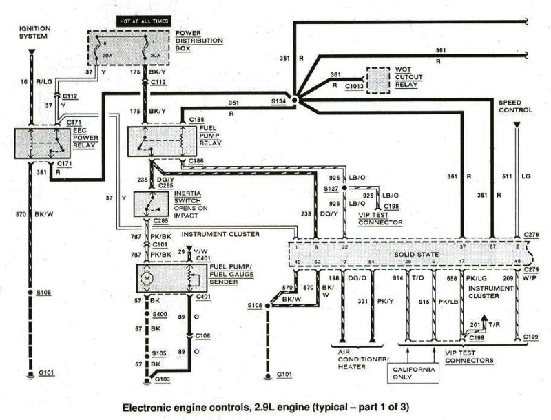
wiring up autometer fuel level gauge - Four Eyed Forums If it's an 86, look for a yellow wire with a white stripe in your dash instrument cluster wiring. That's the one you need to connect to your gauge. The other input on the gauge just needs power, so any switched +12v source will work.

Prosport Performance Series 52mm Fuel Pressure Gauge - Amber / White
Vdo Gauges Wiring Diagram INSTRUCTIONS FOR THE INSTALLATION OF THE ELECTRIC PRESSURE AND/OR FUEL GAUGE ARE CONTAINED HEREIN. (Refer to Diagram C).In addition to gauges, we offer a complete range of fluid level senders, sensors, service parts, accessories and adapters and fittings to help you to meet all your monitoring needs.
Autometer gauges faulty after wiring | Vintage Mustang Forums
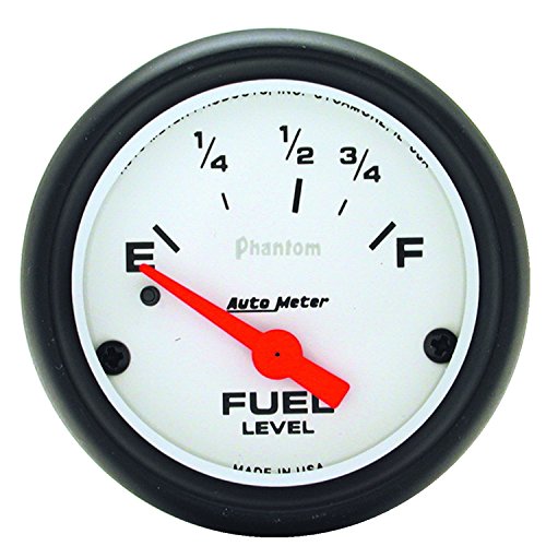
Fuel Level Gauges: Aftermarket, Digital ... - Autometer Fuel Level Gauges: Aftermarket, Digital, Universal & More | AutoMeter 2-1/16" FUEL LEVEL, 16-158 Ω, AIR-CORE, ULTRA-LITE II 2-5/8" FUEL LEVEL, 73-10 Ω, AIR-CORE, PRO-COMP 2-1/16" FUEL LEVEL, 0-90 Ω, AIR-CORE, SSE, CARBON FIBER 2-5/8" FUEL LEVEL, 0-90 Ω, AIR-CORE, GM, SSE, COBALT 2-1/16" FUEL LEVEL, PROGRAMMABLE, STEPPER MOTOR, CHRONO
Top 18 Best Automotive Performance Fuel Gauges of 2022 ...
Autometer Fuel Level Gauge Wiring Diagram - autocardesign Jan 19, 2020 · Autometer Fuel Level Gauge Wiring Diagram – wiring diagram is a simplified all right pictorial representation of an electrical circuit. It shows the components of the circuit as simplified shapes, and the capability and signal friends between the devices. A wiring diagram usually gives guidance practically the relative incline and treaty of ...
2" 52mm Universal Car Fuel Level Level Gauge Red LED Auto ...
Wiring Installation Instructions for : Fuel Level 2 1/16 - Autometer To fuel level sender. PURPLE: Used for triggering (grounding) relay coil when low set point of the gauge is triggered. PROGRAMMING CALIBRATION FOR VARIOUS ...
Project SportRunner
SOLVED: I have a autometer 7114 autometer c2 programmable ... I have a autometer 7114 autometer c2 programmable fuel level gauge purple goes to sending unit wire but i don't have wiring diagram for a 1997 f150 4.2 v6 i have 4 wires 1 large pink/blue, 1large black, 1yellow small,1 small black/orange, from factory unit ,purple to which one? i don't want pull gas tank.

Adjustable Fuel Gauge Tube-Type Fuel Sender | Installation ...
Autometer Gauge Wiring Diagram - Wiring Diagram Nov 19, 2020 · Autometer Pro Comp Ultra Lite Wiring Diagram Fresh Auto Meter Wiring – Autometer Gauge Wiring Diagram. Wiring Diagram arrives with several easy to follow Wiring Diagram Guidelines. It’s intended to aid all the average person in developing a suitable method. These guidelines will be easy to understand and apply.

SpridgetGuru.com-Tech Index-Fuel Gauge Wiring Diagram
SHORT SWEEP ELECTRIC GAUGES - Autometer These gauges can be mounted in-dash or in Auto Meter mounting solutions (panels, cups, pods, etc.). ... 18 gage, wire from fuel tank to gauge.
AutoMeter 5233 Wire Harness - Full Sweep Elec. Fuel Level Gauges
Autometer Gps Speedometer Wiring Diagram For Installing Auto Meter Electric Speedometer, Tachometer, And Short This will require some basic knowledge of automotive electrical, and in some cases a vehicle specific wiring diagram, You may also use this to power a GPS interface. Connect the speedometer wires as shown in the wiring section. 4.
Please Help With Air/Fuel Gauge Install - MY350Z.COM - Nissan ...
PDF Auto Meter Gauges Installation Instructions - CARiD.com Fuel Level. 1. Gauge connects to fuel sender on fuel tank. Existing wires may be used, or route proper length of 18 gage, wire from fuel tank to gauge. If a new hole is drilled in the firewall a grommet is recommended. Connect one end to terminal post on fuel level sender and the opposite end to the sender (S) terminal spade on back of gauge. 2.
AutoMeter 7004 AutoMeter InVision Digital Gauges | Summit Racing
PDF Installation Instructions Short Sweep Electric Gauges Fuel Level 1. Gauge connects to fuel sender on fuel tank. Existing wires may be used, or route proper length of 18 gage, wire from fuel tank to gauge. If a new hole is drilled in the firewall a grommet is recommended. Connect one end to terminal post on fuel level sender and the opposite end to the sender (S) terminal spade on back of gauge. 2.
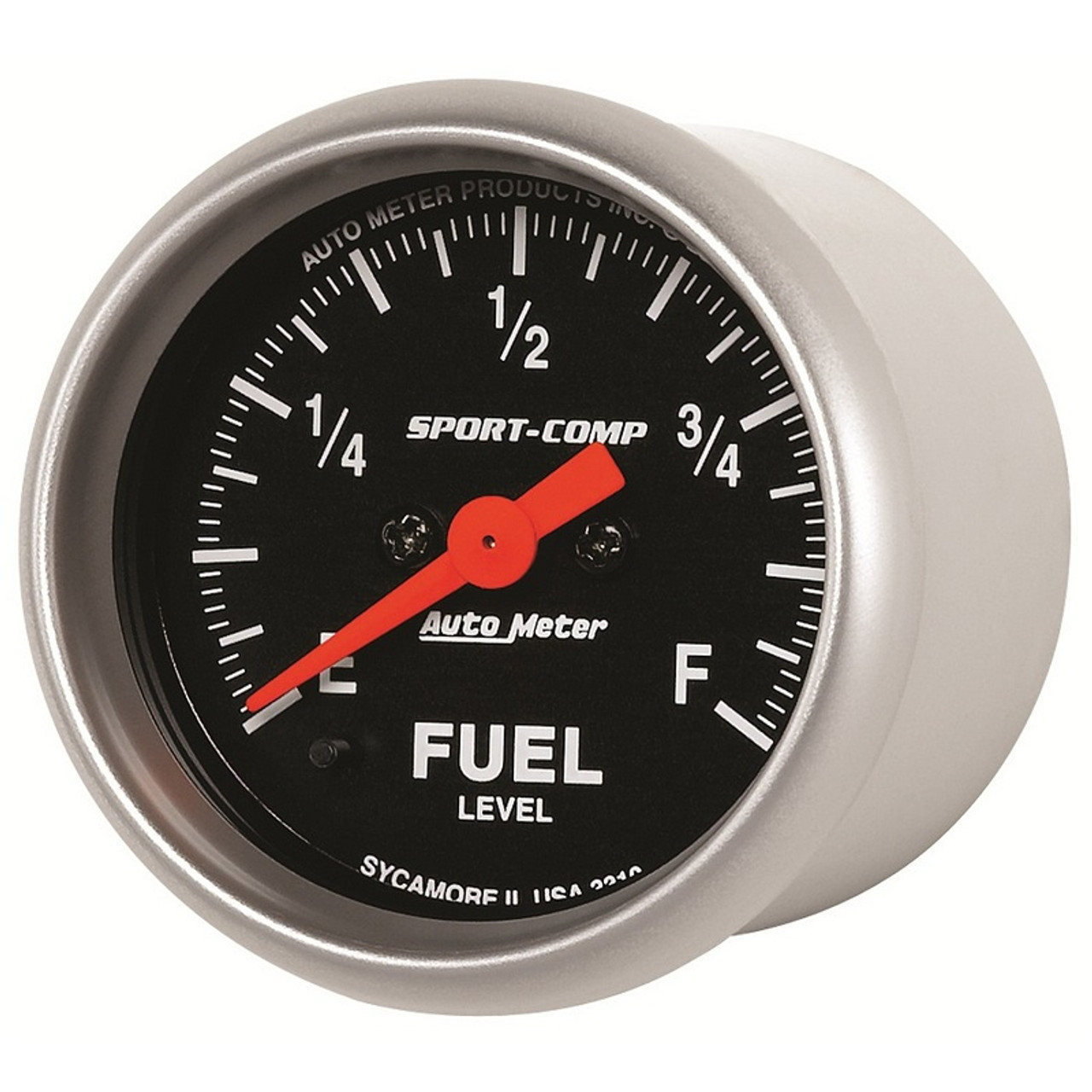
AutoMeter Sport-Comp 2-1/16" Programmable Fuel Level Gauge, 0-280 Ω, Stepper Motor - 3310
Autometer Gauge Wiring Diagram - easywiring Sep 10, 2021 · Wiring diagram for auto meter new wiring diagram auto gauge a newbie s overview of circuit diagrams. Toll free tech support. Pin On Gauges Higginbotham fuel gauge wiring diagram rate fuel gauge wiring autometer gauge wiring diagram additionally wiring diagram provides you with enough time frame by which the assignments are to be accomplished. Autometer …
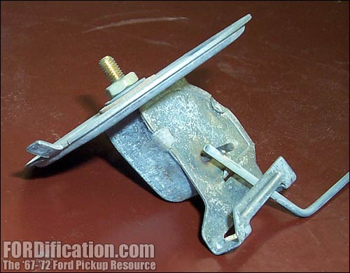
Fuel Tank Sending Unit Tech - FORDification.com
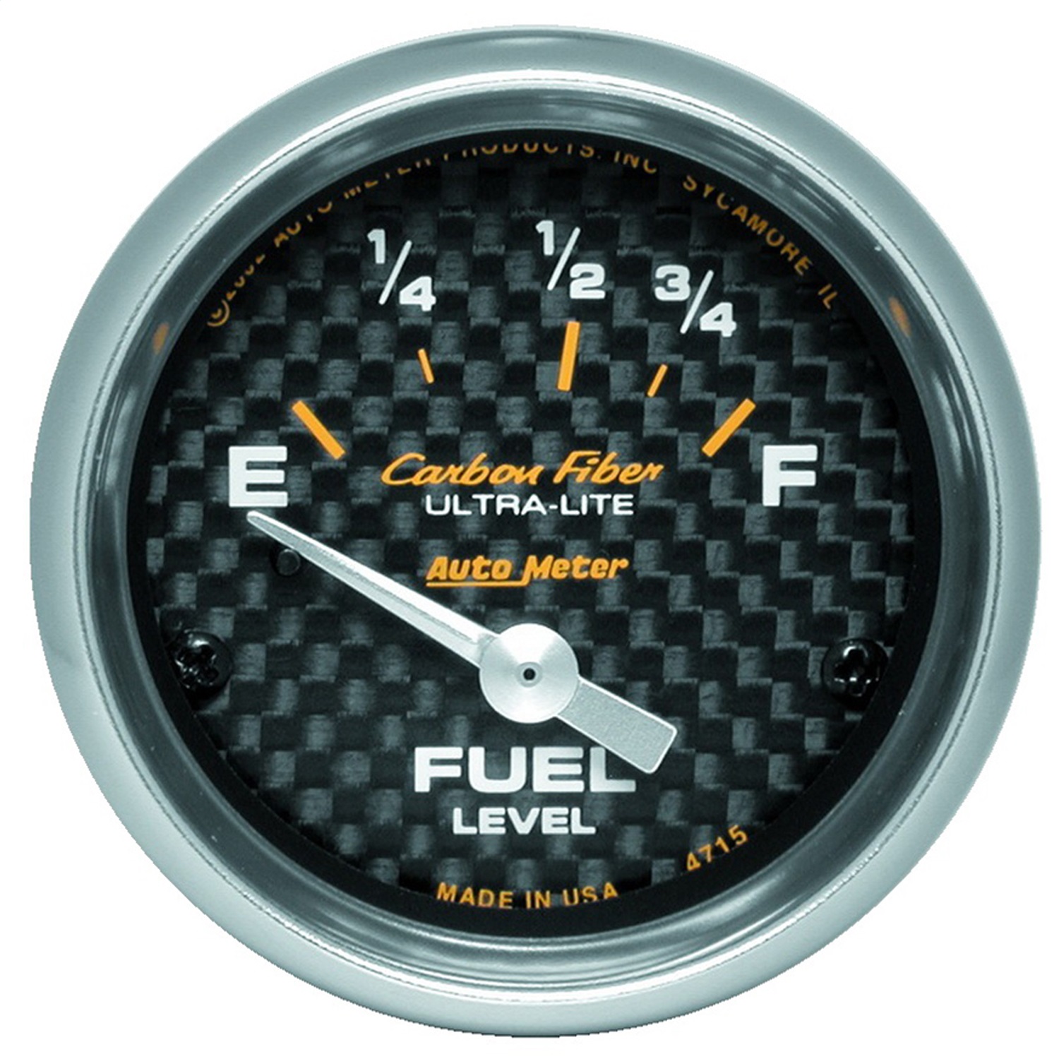
AutoMeter 4715 Carbon Fiber Electric Fuel Level Gauge

Autometer Air Fuel Ratio Gauge Wiring Diagram the purpose of ...

DIGITAL bOOST/vAC GAUGE INSTALLATION INSTRUCTIONS 2650-1236 ...
How to Test and Replace your Fuel Gauge and Sending Unit ...

AM - Cobalt Electric Fuel Pressure Gauge (0~100psi) 6163
How to Test and Replace your Fuel Gauge and Sending Unit ...

How To Diagnose Gauge Problems
White MaxTow 100 PSI Fuel Pressure Gauge

AutoMeter 3514 Sport-Comp Electric Fuel Level Gauge | eBay
Troubleshooting And Replacing Your Ford Fuel Gauge

How to Install an Autometer Volt Gauge

Aftermarket fuel gauge with stock e30 sending unit ...

I changed the fuel sender in my 99 s10 pick up 4.3. i ...
How to Install Auto Meter Oil Pressure Gauge - Electrical ...
A Classic Upgrade To A Vintage Nova Dash
ELITE SERIES fULL SwEEp ELECTRIC fUEL LEvEL gAUgE ...

Auto Meter® - Chrome 2.06" In-Dash Mount Fuel Level Gauge

AutoMeter 3315 Sport-Comp Fuel level Gauge 2-1/16 in., Electrical | eBay
How To Adjust the Fuel Gauge Sender : How-To Library : The MG ...
How to Install Auto Meter Oil Pressure Gauge - Electrical ...
1965 Mustang convertible - fuel gauge dampening - part 2 ...
Fuel Level Gauges Autometer How They Work How To Install Tutorial Instructions Ohms Wiring
0 Response to "42 autometer fuel level gauge wiring diagram"
Post a Comment