42 draw the moment diagram for the beam.
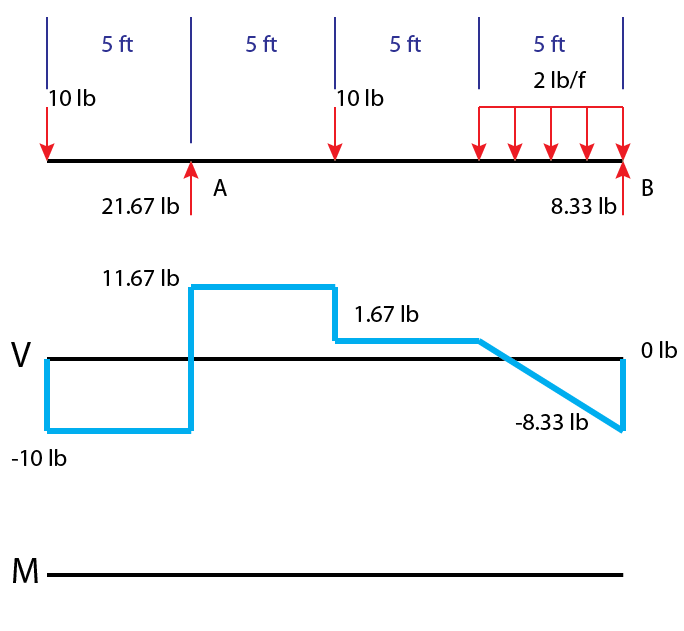
Shear force and bending moment diagram - SlideShare Shear Force and Bending Moments Consider a section x-x at a distance 6m from left hand support A 5kN 10kN 8kN 4m 5m 5m 1m A C D B RA = 8.2 kN RB=14.8kN Ex x 6 m Imagine the beam is cut into two pieces at section x-x and is separated, as shown in figure 3. To find the forces experienced by the section, consider any one portion of the beam. PDF Chapter 4 Shear and Moment In Beams - ncyu.edu.tw The M-diagram reveals that the maximum bending moment is +48 kN·m : the 28-kN load at C. Note that at each concentrated force the V- diagram "jumps"by an amount equal to the force. There is a discontinuity in the slope of theM-diagram at each concentrated force. Sample problem4.2
Answered: Draw the shear and moment diagram for… | bartleby Solution for Draw the shear and moment diagram for the beam. close. Start your trial now! First week only $4.99! arrow_forward learn. write. tutor. study resourcesexpand_more. Study Resources. We ... Draw the shear and moment diagram for the beam. Question. Draw the shear and moment diagram for the beam. Transcribed Image Text: 3m A. Expert ...

Draw the moment diagram for the beam.
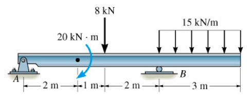
329 6–1. Draw the shear and moment diagrams for the shaft ... 6–9. Draw the shear and moment diagrams for the beam. Hint: The 20-kip load must be replaced by equivalent loadings at point C on the axis of the beam.143 pages PDF 4. Bending Moment and Shear Force Diagram The shear force and bending moment diagram gives a clear picture in our mind about the variation of SF and BM throughout the entire section of the beam. Draw The Shear And Moment Diagrams For The Overhang Beam. How the bending moment diagram of an overhanging beam will be if only we can draw the shear force diagram since it dictates the shape of bending moment . 6-5. Draw the shear and moment diagrams for the beam. 2 m. 3 m. 10 kN. 8 kN. 15 kNm. 6-6. Draw the shear and moment diagrams for the overhang beam. A. 6-5.
Draw the moment diagram for the beam.. PDF Shear and Moment Diagrams - Memphis procedure for constructing the shear and moment diagrams for a beam. 2. To construct the shear diagram, first, establish the V and x axes and plot the value of the shear at each end of the beam. Shear and Moment Diagrams Procedure for analysis-the following is a procedure for constructing the shear and moment diagrams for a beam. Draw the shear and moment diagrams for the beam shown in ... Draw the shear and moment diagrams for the beam shown in Fig. 4-13a. | Holooly.com Support Reactions. The reactions are calculated and indicated on the free-body diagram. Shear Diagram. The values of the shear at the end points A A \left (V_ {A}=+100 \mathrm {lb}\right) (V A = +100 lb) and B\left (V_ {B}=-500 \mathrm {lb}\right) B(V B Draw the shear and moment diagrams for the cantilevered beam The steps required to plot the shear force and bending moment diagrams are: 1. Determine all the reactive forces and couple moments acting on the beam and resolve all of them into components acting perpendicular and parallel to the beam's axis. 2. Mechanics Map - Shear and Moment Diagrams The moment diagram will plot out the internal bending moment within a horizontal beam that is subjected to multiple forces and moments perpendicular to the length of the beam.
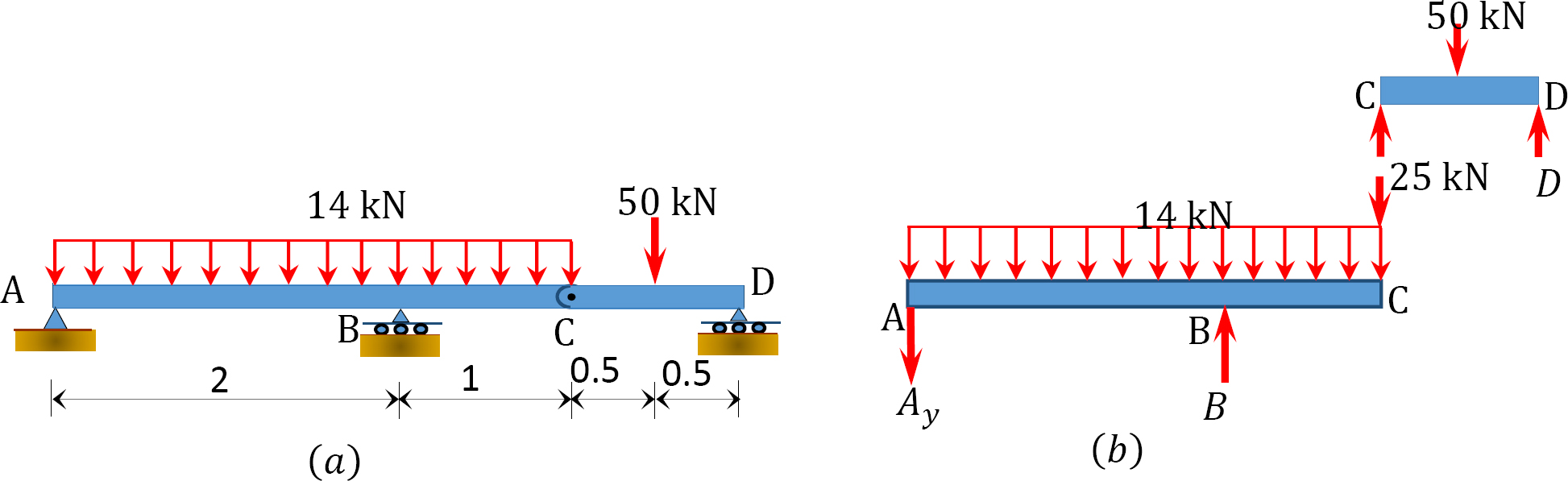
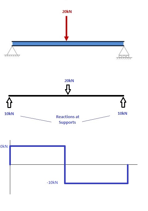
Shear Force and bending moment diagram - ExtruDesign Steps to draw Shear force and Bending moment diagrams In SFD and BMD diagrams Shear force or Bending moment represents the ordinates, and the Length of the beam represents the abscissa. Consider the left or the right portion of the section. Add the forces (including reactions) normal to the beam on the one of the portion. Problem 3: Draw the moment diagrams for the beam | Chegg.com Civil Engineering questions and answers. Problem 3: Draw the moment diagrams for the beam using the method of superposition. Consider the beam to be cantilevered from end C. 30 kN 4 kN/m 80 kN.m C B -8 m - 4m-. Question: Problem 3: Draw the moment diagrams for the beam using the method of superposition. Draw the Shear and Moment diagrams for the beam- With ... 1) Calculate the shear force and bending moment for the beam subjected to concentrated load as shown in the figure. Also, draw the shear force diagram (SFD) and the bending moment diagram (BMD). Solution; Free body diagram of the given figure, Taking moment about point B, R Ay x 4 - 20 x 2 = 0. 4 R Ay = 40. Draw the shear and moment diagrams for the overhang beam ... Draw the shear and moment diagrams for the overhang beam in Fig. 6-16 a . Step-by-Step Report Solution Verified Solution Support Reactions. The support reactions are shown in Fig. 6-16 b . Shear Diagram. The shear of −2 kN −2kN at end A of the beam is plotted at x = 0 x = 0, Fig. 6-16 c .
How To Find Bending Moment In Beams - The Best Picture Of Beam Shear force and bending moment diagrams beam ysis with uniformly bending moments and beam curvatures calculator for beams support reactions bending moment equations ... Bending ering feed how to draw shear force bending moment diagram simply supported beam exles ering intro determine the sf and bm diagrams for simply supported beam shown in fig ... Answered: Draw the shear and moment diagrams for… | bartleby Draw the shear and moment diagrams for the cantilever beam shown and determine the maximum absolute value of the shear and bending moment. Indicate the degree of each curve. You may use the method of sections, area method, or both. 15 kN/m 8 kN 5 kN/m A В 20 kN/m 8 kN/m E 2 m →e 3 m 6 m. PDF CIVL 3121 Shear Force and Bending Moment Diagrams for ... Shear and Moment Diagrams by Superposition Example: Draw the shear and moment diagrams for the following beam using superposition. 10 ft. A 5 k/ft. 10 k (Book Solutions) Draw the Shear and Moment Diagrams for ... Draw the shear and moment diagrams for the beam. Indicate values at the supports and at the points where a change in load occurs. Solution: Check Other Problems' Solutions : Book Solutions for Structural Analysis by R C Hibbeler. As per the Conditions of Static Equilibrium of the Structural Element: ∑Fy = 0, ∑Fx = 0, and ∑M = 0
What is Moment By Parts? — Engineering — WeTheStudy
Draw the shear diagram for the beam. Draw the moment ... Draw the moment diagram for the beam. Draw the moment diagram for the beam. Posted 7 months ago. Q: Can anyone help me to the problem number 6 step by step Thanks . For the beam loading shown using the graphical method, (a) draw the shear and bending moment diagram, (b) state the absolute maximum values of the shear and bending moment.

Draw the shear force and bending moment diagrams for the beam ...
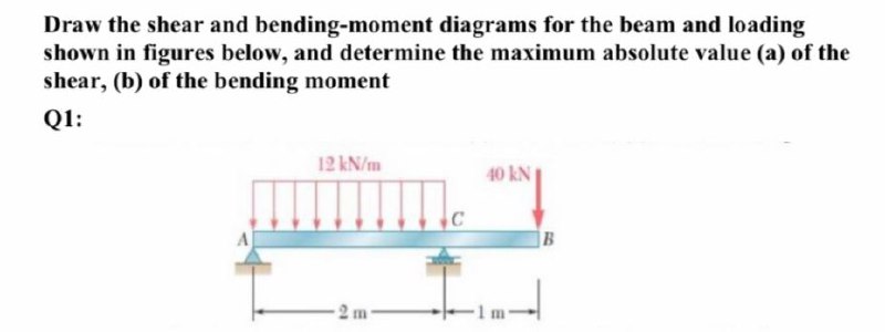
Draw The Shear And Bending Moment Diagrams For The Beam ... Draw the shear force and b.m. Draw the free body diagram of the . 1 answer to draw the shear and bending moment diagrams for the beam and loading shown in figure 4, and determine the maximum absolute value . This is an example problem that will show you how to graphically draw a shear and moment diagram for a beam.
How to Draw Moment Diagrams | ReviewCivilPE
How to Calculate Bending Moment Diagram? | SkyCiv The equation for this part of our bending moment diagram is: -M (x) = 10 (-x) M (x) = 10x Cut 2 This cut is made just before the second force along the beam. Since there are no other loads applied between the first and second cut, the bending moment equation will remain the same.

draw the shear force and bending moment diagram from the beam ...
Free Online Beam Calculator | SkyCiv Engineering The beam reaction calculator and Bending Moment Calculations will be run once the "Solve" button is hit and will automatically generate the Shear and Bending Moment Diagrams. You can also click the individual elements of this LVL beam calculator to edit the model. Beam Reaction Calculator

Statics 7.82 - Draw the shear and moment diagrams for the beam.
Draw the shear-force and bending-moment diagram for the ... Draw the shear-force and bending-moment diagram for the beam shown in Fig. P7.32. Assume the upward reaction provided by the ground to be uniformly distributed. Label all significant points on each diagram. Determine the maximum value of (a) the internal shear force and (b) the internal bending moment.
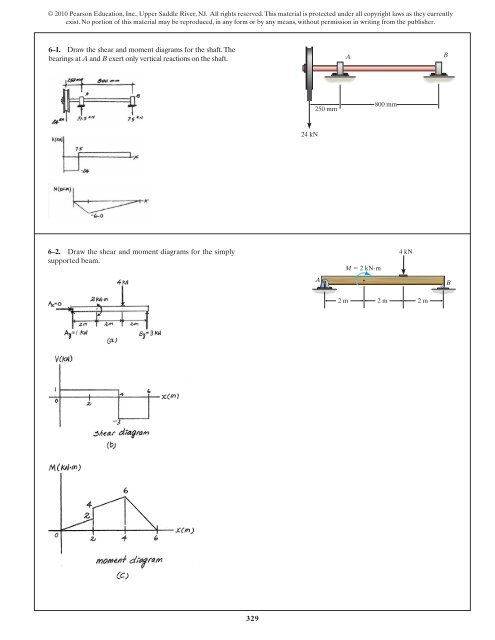
329 6–1. Draw the shear and moment diagrams for ...
Draw The Moment Diagram For Beam - The Best Picture Of Beam Draw The Shear Force And Bending Moment Diagrams For Beam Shown Below Study Hibbeler R C Structural Ysis Solved Draw The Shear Diagram For Beam Follow Sign Convention 1 Transtutors The Ultimate To Shear And Moment Diagrams Degreetutors Draw The Shear And Moment Diagrams For Cantilever Beam In Fig 6 15 A Holooly

Draw the shear and moment diagram for the beam set lef ...
Solved a) Draw the shear diagram for the beam. b) Draw ... This problem has been solved! a) Draw the shear diagram for the beam. b) Draw the moment diagram for the beam. Determine the shear throughout the beam as a functions of x, where 0≤ x <6ft. Express your answer in terms of x. Determine the moment throughout the beam as a functions of x, where 0≤ x <6ft.
The Ultimate Guide to Shear and Moment Diagrams ...
Draw The Bending Moment Diagram For This Beam - The Best ... Draw The Shear Force And Bending Moment Diagrams For Beam Shown Below W 2500 N M F 1 10 000 Study. Solved Draw The Shear Force And Bending Moment Diagrams For Beams 1 Transtutors. Bending Shear And Moment Diagram Graphical Method To. Ultimate To Shear Force And Bending Moment Diagrams Er4 The 1 Source For Ering Tutorials.
6.2 Shear/Moment Diagrams – Engineering Mechanics: Statics
Draw the shear and moment diagrams for the cantilever beam ... Draw the shear and moment diagrams for the cantilever beam.
![Solved] Q1) Draw the axial force, shear force and bending ...](https://s3.amazonaws.com/si.experts.images/questions/2019/12/5defd223e450e_fizik4.png)
Solved] Q1) Draw the axial force, shear force and bending ...
PDF HW 10 SOLUTIONS - University of Utah .7—41. Draw the shear and moment diagrams for the simply supported beam. Since the loading discontinues at the 9- kN concentrated force, the shear and moment equations must be written for the regions O x < 4 m and 4 m < 6 m Of the beam. The free - body diagrams of the beam's segment sectioned through

SHEAR FORCE AND BENDING MOMENT DIAGRAM FOR CANTILEVER BEAM ...
PDF Beam Diagrams and Formulas BEAM DIAGRAMS AND FORMULAS Table 3-23 (continued) Shears, Moments and Deflections 13. BEAM FIXED AT ONE END, SUPPORTED AT OTHER-CONCENTRATED LOAD AT CENTER
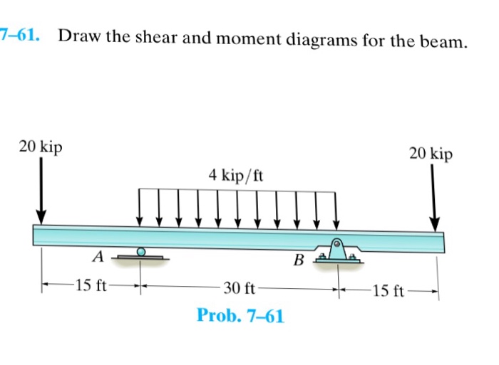
Solved 7-61. Draw the shear and moment diagrams for the ...
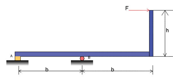
Problem 1: Given: F1 = 4 KN, F2 = 2 KN, a = b ... - chegg.com Transcribed image text: Problem 1: Given: F1 = 4 KN, F2 = 2 KN, a = b = c = 2 m There is a pin at A and roller at B. Draw the shear and moment diagrams for the beam and determine the distance, d, to the right of point A where the internal moment equals zero. In summary, a) Draw the shear diagram and label all pertinent values on the plot b) Draw the moment diagram and label all pertinent ...
Solved Draw the shear and moment diagrams for the beam ...
Draw The Shear And Moment Diagrams For The Overhang Beam. How the bending moment diagram of an overhanging beam will be if only we can draw the shear force diagram since it dictates the shape of bending moment . 6-5. Draw the shear and moment diagrams for the beam. 2 m. 3 m. 10 kN. 8 kN. 15 kNm. 6-6. Draw the shear and moment diagrams for the overhang beam. A. 6-5.

How to draw shear force & bending moment diagram (cantilever ...
PDF 4. Bending Moment and Shear Force Diagram The shear force and bending moment diagram gives a clear picture in our mind about the variation of SF and BM throughout the entire section of the beam.
Draw the shear and moment diagrams for the beam loaded by th ...
329 6–1. Draw the shear and moment diagrams for the shaft ... 6–9. Draw the shear and moment diagrams for the beam. Hint: The 20-kip load must be replaced by equivalent loadings at point C on the axis of the beam.143 pages
1.4: Internal Forces in Beams and Frames - Engineering LibreTexts
329 6–1. Draw the shear and moment diagrams for the shaft ...
How to Calculate Bending Moment Diagram? | SkyCiv
Answered: Draw the shear diagram for the beam.… | bartleby

Draw the shear and moment diagrams for the beam shown in Fig ...

How to Calculate and Draw Shear and Bending Moment Diagrams ...

05.2-1 Shear and moment diagrams graphical method - EXAMPLE

Part A Draw the shear and moment diagram for the beam shown ...
Solved Draw the shear and moment diagrams for the beam ...

How to Calculate and Draw Shear and Bending Moment Diagrams ...
The Ultimate Guide to Shear and Moment Diagrams ...

Draw the shear and moment diagrams for the compound beam ...
329 6–1. Draw the shear and moment diagrams for the shaft ...

Problem 2) Draw the Shear and Moment Diagram for the beam ...

Draw shear and bending diagram for the beam given in the ...
How to draw shear force and bending moment diagrams (strength ...

Draw the shear force diagram and bending moment diagram for ...
Solved] Draw the shear force bending moment diagrams of the ...
Answered: Draw the shear and bending-moment… | bartleby
Draw the shear force diagram of beam, Mechanical Engineering

Draw the moment diagrams for the beam using the method of ...

Bending Moment Diagram - an overview | ScienceDirect Topics
Shear Force & Bending Moment Diagrams - ppt download

Drawing Shear Force, Bending Moment Diagram
How to Draw Shear Force & Bending Moment Diagram | Simply ...
MECHANICS OF MATERIALS
Can you draw the shear force and bending moment diagrams of ...
0 Response to "42 draw the moment diagram for the beam."
Post a Comment