38 crydom solid state relay wiring diagram
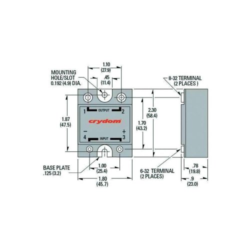
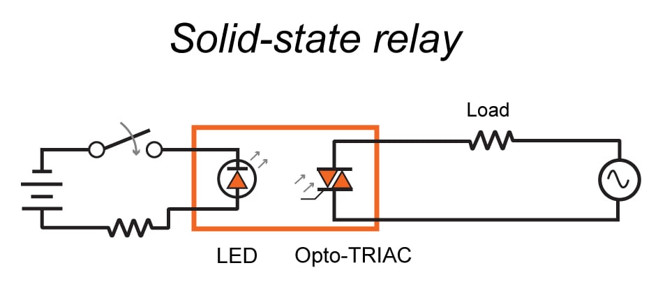
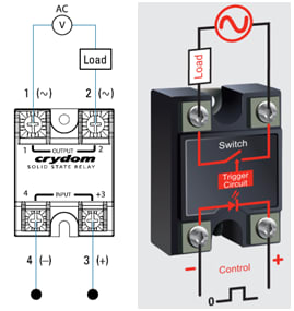
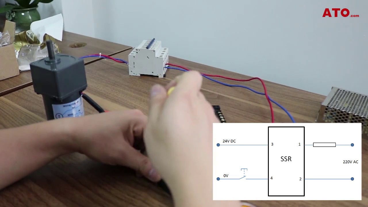
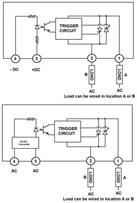
PDF DataSheet Panel Mount Contact Crydom Technical support for information on the availability of a specific part number. * ... WIRING DIAGRAM AC V Load (10) 1 ( ) 2 ( ) 1 OUTPUT 2 SOLI D STATE RELA Y 4 INPUT 3 ... SOLID STATE RELAY OUTPUT INPUT Mounting Hole/Slot 0.19 [4.9] DIA. 0.49 [12.4] Faston Terminal(13) 0.25 x 0.032 Solid State Relays: A Basic Overview Looking at the physical wiring diagram for the solid-state relay below, you can see that the equipment has parameters 1, 2, 3, 4, and 60A. 60A of which represents the indicator light in action (there are two states, on and off).
The Complete Guide To Solid State Relays | RS Components This complete guide looks at what solid state relays are, how they work, the various circuits and the different types that are currently available.
Crydom solid state relay wiring diagram
Crydom D2425 25A Solid State Relay - Price, Specs This is a custom part featuring a Crydom D2425 25A Solid State Relay and HB Controls Heatsink. Crydom D2425 Configuration: • Input: 3-32 VDC • Output: 240 VAC • 3 Phase / 2 Pole Configuration • Finger Safe Covers HB Controls L Series Datasheet (pdf) HB Controls Assembly Wiring Diagram (pdf) Crydom D2450-10 Solid State Relay Wiring Diagram The diagram below shows how to wire a solid state relay. Please note that the diagram refers to DC/DC type solid state relay (SSR). Solid State Relay (DC/DC): Connect (R) positive terminal to the push button switch. Connect (R) negative terminal to the negative terminal on battery 1. Perfect Solid State Relay Wiring Diagram 2004 F150 Starter Dc solid state relay wiring diagram 1 1 dc to dc solid state relay. Hella solid state relay pn. The output of the relay immediately begins to conduct load current point 2 as opposed to a zero crossing relay which will wait until the next zero cross point of the ac sine wave.
Crydom solid state relay wiring diagram. PDF Installation Sheet DIN Rail Mount - Crydom The air gap is the clearance distance adjacent to either side of the relay or assembly measured to the next closer relay or assembly. 100% Duty Cycle. Rev: 121113 WIRING DIAGRAM +3/A1 4/A2 1/L1 2/T1 Load (+/ ) ( / ) SOLID STATE CONTACTOR Connecting Crydom MOSFET Solid State Relays How to connect solid state DC relays focusing on Crydom made devices. Includes circuit examples. CRYDOM Solid State Relays - Grainger Industrial Supply When it comes to CRYDOM Solid State Relays, you can count on Grainger. Supplies and solutions for every industry, plus easy ordering, fast delivery and 24/7 customer support. How to Bench Test a Solid State Relay - Crydom January 1, 2010 - Your full source for switching solutions in our Solid State Relays and Solid State Contactors product line. View full specifications, drawings and more available for you to download.
Datasheet - ManualShelf DUAL Series • Independently controlled dual output solid-state relay • Ratings ... WIRING DIAGRAM THERMAL DERATE INFORMATION AGENCY APPROVALS Designed in ... Panel Mount SSR: Series 1 120 VAC - Crydom Our over 40 years’ experience as Solid State Relay manufacturing leader allows us to provide our customers with the widest range of standard Solid State Relays and Contactors, custom designed products, accessories and assemblies; whenever an industrial application may benefit of the advantages ... PDF Solid State Relays - Omega Engineering to failure due to overload and improper initial wiring. Solid state relays can fail, contact closed, on overload circuits. It is essential that a properly rated, fast blowing I2T fuse be installed to protect the load circuit Finned heat sinks are anodized fabrications that come complete with tapped mounting holes and screws. Crydom Dual Solid State Relays - Steven Engineering Steven Engineering is among the largest distributors of electronics & industrial automation components and electric parts, offering over 130,000 product types from leading manufacturers.
Your source for Solid State Relays and Solid State Contactors ... Your full source for switching solutions in our Solid State Relays and Solid State Contactors product line. View full specifications, drawings and more available for you to download. AC Output SSRs - Installation Sheet Your full source for switching solutions in our Solid State Relays and Solid State Contactors product line. View full specifications, drawings and more available for you to download. Using a Solid State Relay - Learn how to wire a solid ... The diagram below shows how to wire a solid state relay. Please note that the diagram refers to DC/DC type solid state relay (SSR). Solid State Relay (DC/DC): Connect (R) positive terminal to the push button switch. Connect (R) negative terminal to the negative terminal on battery 1. Using Solid State Relays in parallel and/or series - Crydom Your full source for switching solutions in our Solid State Relays and Solid State Contactors product line. View full specifications, drawings and more available for you to download.
Crydom solid state relays, 20 to 100A, 72 to 300V, MOSFET ...
power-plus-dc-series-100-dc-panel-mount.pdf - Crydom Our over 40 years’ experience as Solid State Relay manufacturing leader allows us to provide our customers with the widest range of standard Solid State Relays and Contactors, custom designed products, accessories and assemblies; whenever an industrial application may benefit of the advantages ...

Crydom D2425 25A Solid State Relay - Price, Specs
Crydom D2425 Wiring Diagram Collection DOWNLOAD. Wiring Diagram Pictures Detail: Name: crydom d2425 wiring diagram - Banner Solid State Relay Q45bw22dq1 Wiring Diagram Wiring Data on pilz relay wiring. File Type: JPG. Source: 919ez.info. Size: 454.64 KB. Dimension: 2320 x 3408. Variety of crydom d2425 wiring diagram.

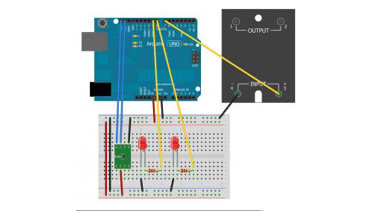
SSR(Solid State Relay) Interfacing with Arduino: Auto AC(Air ...
12 24 D DR R 06 24 D DRD R - Crydom Your full source for switching solutions in our Solid State Relays and Solid State Contactors product line. View full specifications, drawings and more available for you to download.
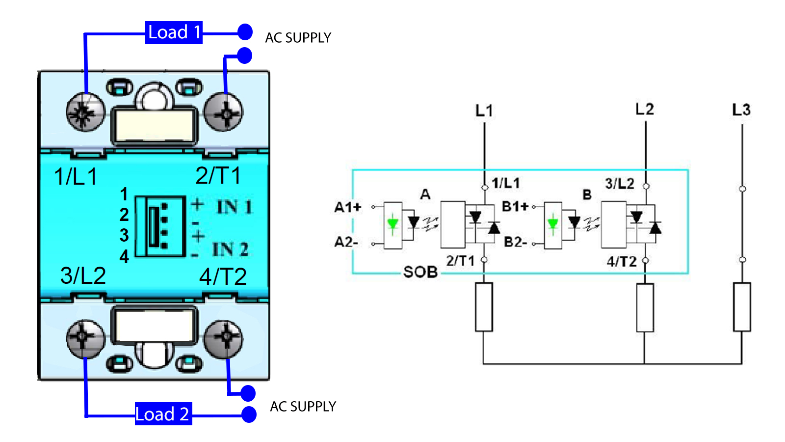
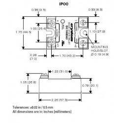
SOB range - Two-phase SSR - celduc® relais
Crydom solid state relays | Mike Holt's Forum Location. Placerville, CA, USA. Occupation. Retired PV System Designer. Oct 23, 2018. #5. :thumbsup: Mechanical relays have an unavoidable hysteresis because of the moving armature. Solid state relays will generally design in similar hysteresis, even when it is not an inherent feature of the gate elements themselves.

SSR Filter EMI Noise Suppression Filter for use with Crydom Three Phase SSR's
Crydom Solid State Relay Wiring Diagram - Wiring Diagram Crydom Solid State Relay Wiring Diagram. By Admin | October 16, 2018. 0 Comment. Connecting crydom mosfet solid state relays ssr relay interfacing with arduino auto ac air conditioner on off switch the global expert in technology panel mount manualzz el100d10 05 10 a 100 vdc quick connect dc how to test using electrical mechanical info facebook ...
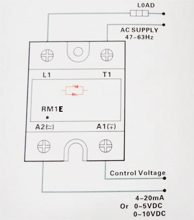
RM1E23AA25 5pcs 1 Phase AC SSR Solid State Relay,Industrial ...
PDF SOLID STATE RELAY SELECTION GUIDE - Sensata Solid State Relays Series Description 0.1 3 3.5 5 6 10 12 20 30 DRA-CN 6 mm DRA 10/54 mm SeriesOne DR 11/18 mm NOVA22 DR22 22.5 mm Solid State Relay Timers SeriesOne DR Timers11 mm Solid State Contactors DRA4D Reversing SSC Solid State 3 Phase Relays NOVA22 DR67 3 Phase SOLICON DRC3P 3 Phase SOLICON DRC3R Reversing DRH 3 Phase IEC OTP Solid ...
Crydom D06D60 Solid State Relay: Amazon.com: Tools & Home ...
Solid State Relays | Sensata Technologies Sensata | Crydom has a broad offer of Solid State Relays and Contactors in several different mounting styles, covering a wide range of voltage and current ratings. Our Solid State Relays can be used to control almost any type of load in demanding heating, lighting, motion and power control applications that can benefit from the many advantages that SSRs have over traditional electromechanical ...
The Basics of SSRs (Solid-State Relays): The Switching Device ...
70 Amp Sub Panel Wiring Diagram - easywiring 70 Lovely Crydom Solid State Relay Wiring Diagram In 2020 Relay Ac Wiring Spot Welder . Testing A Circuit Breaker Panel For 240 Volt Electrical Service Home Electrical Wiring Electrical Panels Electrical Wiring . Wiring Safety Relay Pilz Pnoz And Emergency Stop Button In 2020 Relay Emergency Current Transformer
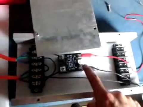
Solid State Relay Test
PDF Installation Sheet DIN Rail Mount - Crydom Crydom CTR Series Solid State Relays were developed to offer the advantages of semiconductor ... Wire Size Maximum wire size of AWG #16 (1.3 mm2) on input and AWG #8 ... Recommended Screw Torque Range 4.4 in-lbs (0.5 Nm) on input and 12 in-lbs (1.3 Nm) on output. WIRING DIAGRAM Rev: 082316 Installation SheetDIN Rail Mount. Title: IS_CTR Author:

SMR2450-6
PDF Solid State Relays Common Precautions - Omron Solid State Relays Common Precautions Solid State Relays Common Precautions 3.ON/OFF Frequency An SSR has delay times called the operating time and release time. Loads, such as inductive loads, also have delay times called the operating time and release time. These delays must all be considered when determining the switching frequency. 4.Input ...
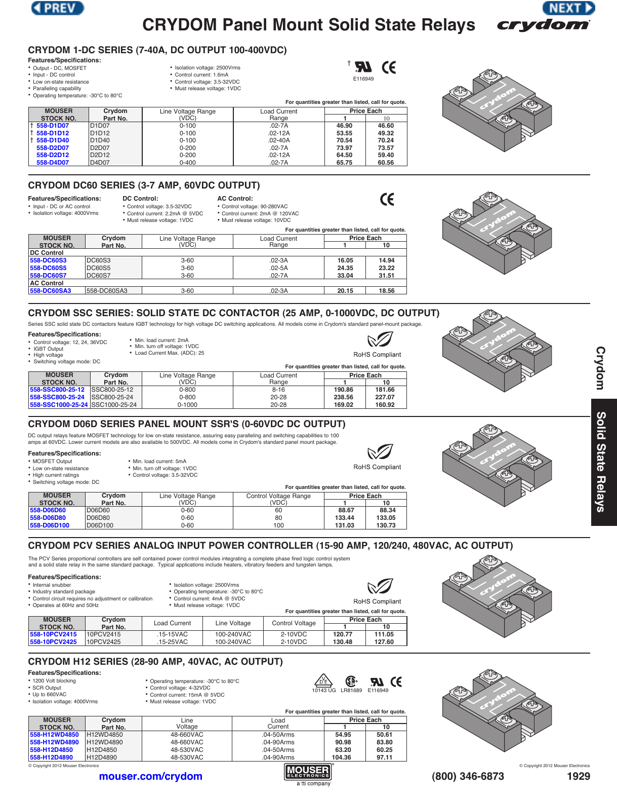
CRYDOM Panel Mount Solid State Relays | Manualzz
Solid State Relay Types - ncd.io DC Solid State Relays are Polarity Sensitive! Please see our Wiring Diagram for DC SSRs: dc_solidstate_diagram. Type E: Crydom PF480D25. 25A 240VAC Normally Open SPST. Zero-Cross Turn On. For Use with Inductive Loads. AC Switching ONLY. .06A Minimum Load Required. -30 to 80°C Operating Temperature.
Panel Mount Solid State Relays Vol. II
CWA4850E Crydom Co., CWA4850E Datasheet - Elcodis Models SST120 and SST240 control modules gradually apply power to the load when energized by the control voltage. They must be used with Crydom Series 1 random turn-on solid state relays. Consult factory for SST wiring diagrams and about use with 480 Vac loads. For a complete set (control module and solid state relay) order 10SST120, 25SST120 ...

7 Solid Reasons to Use Solid State Relays | Engineering.com
Installation Sheet - Crydom Your full source for switching solutions in our Solid State Relays and Solid State Contactors product line. View full specifications, drawings and more available for you to download.

70 Fresh 24v Switching Relay Wiring Diagram | Relay, Diagram ...
Crydom - The Global Expert in Solid State Relay ... - Steven ... Steven Engineering is among the largest distributors of electronics & industrial automation components and electric parts, offering over 130,000 product types from leading manufacturers.
Crydom - The Global Expert in Solid State Relay Technology
Power Over Ethernet Ip Camera Wiring Diagram Power over ethernet ip camera wiring diagram. Paper focuses on the approach to optimize the ip video network with power over ethernet. This allows devices like security cameras phones network switches or antennas to send and receive data and power with just one cable. The two standard types of poe are 8023af and 8023at.
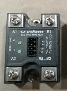
Details about Crydom CD4825W3V Relay #022D17
Crydom Solid State Relays & Contactors Short Form Catalog Steven Engineering is among the largest distributors of electronics & industrial automation components and electric parts, offering over 130,000 product types from leading manufacturers.

70 Lovely Crydom solid State Relay Wiring Diagram | Relay ...
Crydom Solid State Relays by SYNsCON - Issuu They must be used with Crydom Series 1 random turn-on solid state relays. Consult factory for wiring diagrams and about use with 480 Vac loads. For acomplete set (control relay and solid state ...

RSSDN-90A-IDEC
Solid State Relays - Crydom | DigiKey June 19, 2012 - Crydom's solid state relays including defining SSR, the types of SSRs available, and typical applications.
7 Solid Reasons to Use Solid State Relays | Engineering.com
Crydom D2425 Wiring Diagram - schematron.org Crydom's DPA solid state relays are compact pin DIP packages that are ideal Consult factory for wiring diagrams and about use with Vac loads. This Crydom D 25A Solid State Relay is new from surplus stock. This is a custom part HB Controls Assembly Wiring Diagram (pdf) · .
Crydom Three phase solid state relay A53TP50D- 50A 530VAC
Crydom - Solid State Relays - Amazon.com Free delivery on millions of items with Prime. Low prices across earth's biggest selection of books, music, DVDs, electronics, computers, software, apparel & accessories, shoes, jewelry, tools & hardware, housewares, furniture, sporting goods, beauty & personal care, groceries & just about anything else.
Super Easy PC Control of 110 Vac Using a Crydom Solid-State ...
Bump Box Using SSR - Page 5 - Holley Bump Box Using SSR. Yeah, it's gotta go to the Holley first and let the Holley trigger the transbrake. You can't have it on both sides, you get a weird voltage drop from the lights, and it won't work right. So just take the reverse Light switch wire, and go to a pin on the Holley ECU.

Variable resistance SSR for boil control? | Homebrew Talk ...
Crydom Solid State Relays | D2425 | HBControls Crydom Panel mount solid-state relay, DC input, zero-crossing 240Vac / 25A output @ 40C, Direct-bond copper (DBC) substrate for superior thermal performance, Direct-power lead-frame design reduces solder joints and enhances reliability
An Introduction To Solid State Relays | Hackaday
EL Series Improved Design Press Release | Crydom Crydom presents the redesigned range of EL Series AC and DC output solid state relays with ratings up to 30 Amps, making it the highest current rating SSR in this compact footprint. The EL Series SSR comes in a 21mm x 35mm housing with quick connect terminals, ideal for applications where space ...
Solid State Relay Wiring
Panel Mount Series 1 240 VAC Solid State Relay - Crydom Our over 40 years’ experience as Solid State Relay manufacturing leader allows us to provide our customers with the widest range of standard Solid State Relays and Contactors, custom designed products, accessories and assemblies; whenever an industrial application may benefit of the advantages ...

Connecting Crydom MOSFET Solid State Relays
CX240D5 - Sensata/crydom - Solid State Relay, SPST-NO, 5 A The CX Series SIP Solid State relay is ideally suited for high density PCB applications where a maximum of 5A of current is required. The SSR utilizes a back-to-back SCR output which provides added reliability in commercial and heavy industrial applications. The SSR had a high surge current rating and is available with a Zero Voltage (resistive loads) or Instantaneous Turn-On (inductive or ...
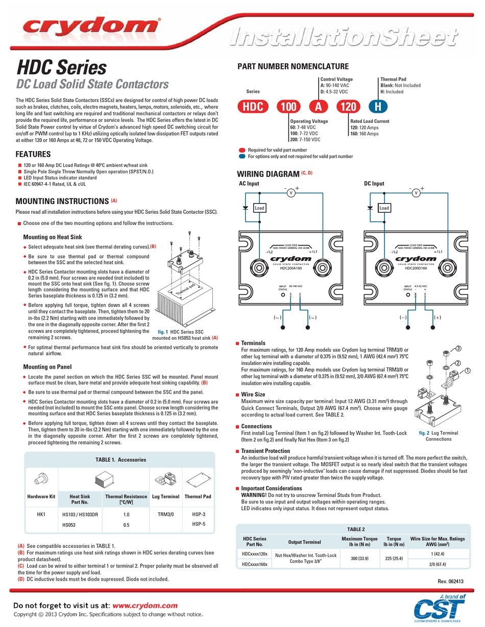
CST CRYDOM HDC SERIES INSTALLATION SHEET Pdf Download ...
Crydom TechLab 1 - How to perform an operational on-off ... Episode 1 of the Crydom TechLab Video Series shows the basic connections necessary to install a Solid State Relay as well as the step by step process on how ...

220V Heatbed + Crydom D2425 Relay + DuetWifi Wiring ...
Crydom - The Global Expert in Solid State Relay Technology WIRING DIAGRAM. MAXIMUM SURGE VS DURATION. AGENCY APPROVALS. UL E116950 (100 Volt Models 1-DC Only ). Rev. 121608. Courtesy of Steven Engineering, ...
Using Arduino tide predictions - Home Automation
D2440 - Sensata/crydom - Solid State Relay, SPST-NO, 40 A The D2440 is a Solid State Relay with aluminium base plate, 94V-0 housing, SPST-NO contact, zero crossing switching mode and screw terminals. This series-1 panel mount relay features improved SEMS screw and washer, redesigned housing with anti-rotation barriers.
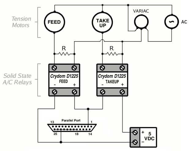
OPCS - Tension Motor Wiring
D2450 Solid State Relay-Crydom - TodayComponents.com Crydom D2450 @ $34.00 from TodayComponents Only $34.00. Same-Day Shipping! SSR; Zero-Switching; SPST-NO; Cur-Rtg 50A; Ctrl-V 3-32DC; Vol-Rtg 24-280AC ,Relay Crydom D2450Series 50 A 24 to 280 V Zero Cross DC Control Solid State Relay Pane
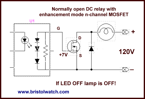
Connecting Crydom MOSFET Solid State Relays
PDF Solid-State Relays Data Sheet - Opto 22 to deliver a low-cost, 10-amp, solid-state relay in an all-plastic case. The push-on, tool-free quick-connect terminals make the Z Series ideal for high-volume OEM applications. Operating temperature: -40 °C to 100 °C. See page 7. Printed Circuit Series SSRs Opto 22's Printed Circuit Series allows OEMs to easily deploy solid-state relays on
Crydom 50 A Solid State Relay, DC, Panel Mount, 280 V rms Maximum Load
Perfect Solid State Relay Wiring Diagram 2004 F150 Starter Dc solid state relay wiring diagram 1 1 dc to dc solid state relay. Hella solid state relay pn. The output of the relay immediately begins to conduct load current point 2 as opposed to a zero crossing relay which will wait until the next zero cross point of the ac sine wave.
Crydom Solid State Relays & Contactors Short Form Catalog
Crydom D2450-10 Solid State Relay Wiring Diagram The diagram below shows how to wire a solid state relay. Please note that the diagram refers to DC/DC type solid state relay (SSR). Solid State Relay (DC/DC): Connect (R) positive terminal to the push button switch. Connect (R) negative terminal to the negative terminal on battery 1.

Connecting Crydom MOSFET Solid State Relays
Crydom D2425 25A Solid State Relay - Price, Specs This is a custom part featuring a Crydom D2425 25A Solid State Relay and HB Controls Heatsink. Crydom D2425 Configuration: • Input: 3-32 VDC • Output: 240 VAC • 3 Phase / 2 Pole Configuration • Finger Safe Covers HB Controls L Series Datasheet (pdf) HB Controls Assembly Wiring Diagram (pdf)
MCX PCB Mount SIP Solid State Relays - Crydom / Sensata | Mouser
An Introduction To Solid State Relays | Hackaday

Solid
Solid State vs. Electromechanical Relays | Arrow.com

Wiring Soild State Relays - G4+ - Link Engine Management Forums
0 Response to "38 crydom solid state relay wiring diagram"
Post a Comment