39 current sensing relay circuit diagram
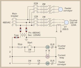
The circuit in Fig. 1 below illustrates the electrical arrangement to accomplish this design. Fig. 1. The current relay with an overcurrent setpoint provides protection and enhanced functionality for this rock crushing equipment arrangement. Material is fed to the crusher by the feeder conveyor, which can overload the crusher with excess material. ACS712 Current Sensor: Features, How it works, Arduino ... If you're looking for a current sensor that supports both AC and DC yet retaining performance advantages over the ACS712, the above Grove - ±5A DC/AC Current Sensor (ACS70331) is your pick! Based on Allegro's high sensitivity current sensor IC; ACS70331EESATR-005B3, it's suitable for <5A current sensing applications, alongside its base sensitivty of 200mV/A!
Simple Musical LEDs Circuit Diagram 2016-02-26 · Automatic Street Light Controller Circuit Using LDR and Relay. Panic Alarm Button Circuit using 555 Timer IC. ... Driving 100 LEDs need approx 2A current (20mA per LED), so you also need to change transistors and other components accordingly. ... Put the circuit exactly as shown in the circuit diagram, it will work for sure.

Current sensing relay circuit diagram
Voltage Sensor Circuit - isolated voltage sensor power ... Voltage Sensor Circuit - 16 images - results page 2 about sensors searching circuits at, hev tv 1 7 high voltage battery pack temp sensors youtube, what are different types of sensors with circuits, p0641 sensor reference voltage a circuit open, Current Sensing Circuit : 5 Steps - Instructables Ways to measure current: 1- Indirect method: such as current transformers (in the figure) and Hall effect sensors, which relies on Faraday's law of induction to sense current in a circuit and convert it to a proportional voltage. These methods are suitable more for high current systems. 2- Direct method: which relies on Ohm's law which states that V = I x R. Current Sensor Relays - Grainger Industrial Supply Current sensor relays detect voltage changes and switch power on or off. They protect heavy machinery from damage from overloads, undercurrents, and lamp loads. Note: Product availability is real-time basis and adjusted continuously. The product will be reserved for you when you complete your order.
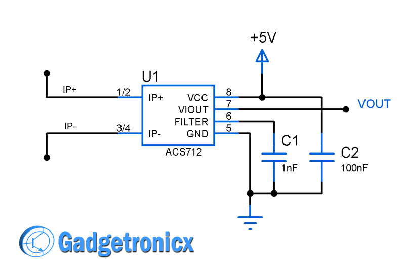
Current sensing relay circuit diagram. Motion Activated PIR Relay Circuit - Making Easy Circuits Following is an ordinary circuit that activates a relay when a living being (a human) is detected by the PIR sensor. Here PIR symbolizes Passive Infrared sensor. It doesn't deliver any infrared radiations to sense the occurrence of a living being but meanwhile it detects the infrared radiations released by them. Relay and Relay Circuits Schematic Circuit Diagram Door Circuits: Various door circuits can be made by controlling the current flow with the relays. The example circuits are given below. The example circuits are given below. In the three relays given in Figure 1.10, if the bobbins are energized, they will draw their pallets to them and the current at the output will reach the current. 3 Simple Proximity Sensor Circuits Circuit Diagram Parts List fro the proposed IC 555 based IR proximity detector circuit. 2-- IC LM 555 2-- IC sockets 8 pin 1-- relay 12 V 5 pin 1-- Infrared Phototransistor General Purpose 1-- Infrared Diode General Purpose 3-- BC547 2-- capacitors. 10 uF / 50 V 1-- 1N4148 diode 1-- red led 5mm 1-- 68 H 1-- 1K5 2-- 10K 1-- 100K Current sensor switch circuit - Gadgetronicx The IC ACS712 is a low cost hall effect current sensor which is capable of measuring current up to 20 Amperes. This IC consist of a copper conduction path through which the current to be measured flows. The output voltage will be proportional to the input current flow. Also the output voltage of this IC will go through a change of 100mV/A.
PDF Current Sensing Relay - Sylvane Model A50 Current Sensing Relay CAUTION: For proper operation, the wire lead sponge bracket must carry a minimum of 4.0 amps. If the current draw is less than 4.0 amps, wrap the lead wire around the bracket so that it passes between the bracket and relay housing two or more times. Current Sensing Switches (Current Sensing Relays) | NK ... AC CURRENT SENSING SWITCH SELECTION PLC or DCS Input Relay or Contactor Control Very Low AC Current Detection Adjustable Delay on Current Rise Inrush Delay Plus Adjustable Delay on Current Rise Analog Output Plus Limit Alarm Contact Dual Setpoint, Dual SPDT Relay Outputs CURRENT SENSING SWITCH SELECTION BY SERIES AS0 Series AS1 Series Direct Online Starter – DOL Starter Wiring Diagram for Motors A simple fuse or circuit breaker cannot protect the system from overloading because they are used for overcurrent (short circuit) protection. The OLR has current sensing properties that can differentiate between the starting and overload current. Related Post: Main Difference between Contactor and Starter; DOL Starter Wiring Diagram: Ford F150 (2009-2014) Fuse Diagram - FuseCheck.com Fuse box diagram (fuse layout), location and assignment of fuses and relays Ford F150 / F-150 SVT Raptor / Ford Lobo (2009, 2010, 2011, 2012, 2013, 2014).
Over load monitoring and Protection using Arduino & ACS712 ... This is the ACS712 current sensor. as you can see it has three male headers labeled as vcc..out and ground…vcc will be connected with the Arduino's 5v..the out pin will be connected with the Arduino's Analog pin A1 and the ground will be connected with the Arduino's ground.. over load monitoring Circuit Diagram: Current Sensor Module - ACS712 - Circuits DIY ACS712 current sensor module can measure the current passing through a node. ACS712 is a compact size module with the simplest interface. Working with the ACS712 sensor primarily based on Hall Effect Principle. ACS712 module can measure both the Alternating Current (AC) and Direct Current (DC) ranging from -5A to +5A, -20A to +20A and -30A to +30A. Current Sensing Relay Circuit Diagram - Studying Charts Current sensing relay wiring diagram current sensing relay circuit diagram best of i2c relay control rh nawandihalabja 12V Relay Wiring File Type. The following current sensing circuit is capable of measuring electrical current in 500 volts system. How it Works. Two external Mosfets is added to hold off the voltage allows the LTC6101. How to use relay with schematic of relay circuit diagram Basic schematic circuit diagram of Relay. The following schematic shows the basic circuit. Connect the relay with HC11 port pins this is used to control on switches. The transistor allows the HC11 to control the medium sized coil current of relay. The diode prevents relay from arcing by giving a return path for the energy stored in the magnetic ...
schematics - current sense switch - Electrical Engineering ...
Automatic Street Light Controller Circuit Using Relays and LDR 2012-03-09 · Description. The circuit diagram present here is that of a street light that automatically switches ON when the night falls and turns OFF when the sun rises.In fact you can this circuit for implementing any type of automatic night light. The circuit uses a Light Dependent Resistor (LDR) to sense the light .When there is light the resistance of LDR will be low.

AN-105: Current Sense Circuit Collection Making Sense of ...
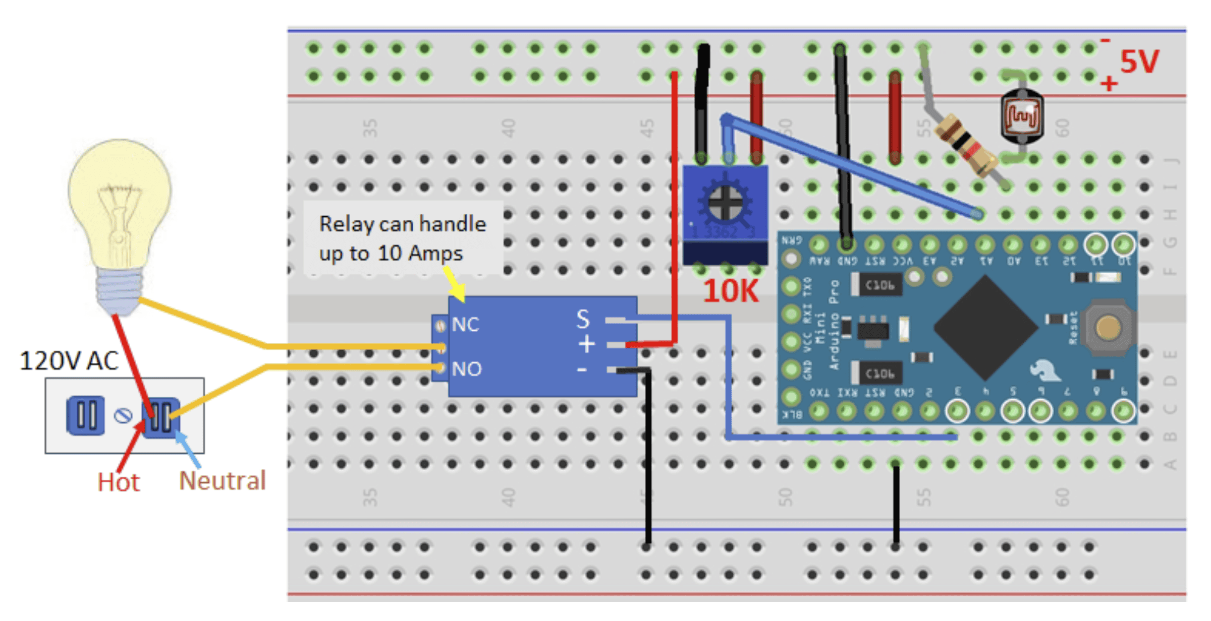
Arduino Relay for Beginners: Control High-Voltage Circuits ... The relay consists of two unrelated circuits - control circuits A1 and A2 and controlled circuit 1, 2 and 3. There is a metal core between A1 and A2. An anchor (2) will be attracted to it if an electric current is applied to it. 1, 3 - fixed contacts.

Current sensing relay with delay on break for dust collection ...
Simple Relay Switch Circuit Diagram In this relay circuit we use a push button to trigger a 5V relay, which in turn, complete the second circuit and turn on the lamp. Material Required Relay 5V Bulb Holder CFL Push ON/OFF Button Perf-Board 9V battery AC supply Relay Switch Circuit Diagram Working of the Basic 5V Relay Circuit In the above circuit, 5V relay is powered by a 9V battery.

Macromatic CAH05A2AE 0.5-5A 120V Current Sensing Relay
PDF Installation Instructions for Models 50 and 51 Current ... Install the Model 51 on the common wire of the blower motor as shown in the diagram. 3. Open the main power junction box on the side of the furnace. Run the leads of the Model 51 relay into the junction box. 4. Connect the leads of the Model 51 relay in series with one of the electronic air cleaner leads.
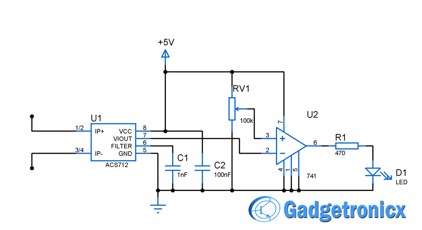
Current sensor switch circuit - Gadgetronicx
LM741 Light Sensor Relay Switch - Circuits DIY A light-sensing relay switch in a wide variety of renewable energy projects is extremely useful and flexible, from automatic lighting to protection systems. The diagram below shows the proper figure of the LM741 light sensor relay switches circuit project/schematic. The circuit is pretty sensitive and activates the relay when a small amount of ...

Current sensor circuit diagram | Download Scientific Diagram
CR4395 AC Current Sensing Relay - CR Magnetics The CR4395 series Current Sensing Relay provides an effective and highly stable method for monitoring electrical current. The current-carrying wire is routed through the opening extending from the top of the case. When current reaches the level set by the trip point adjustment, the relay trips and starts the adjustable timer.

Design of self-powered TMR current sensor: (a) schematic ...
Current Sensing Relay Wiring Diagram Gallery - Wiring ... Please download these current sensing relay wiring diagram by using the download button, or right visit selected image, then use Save Image menu. Wiring diagrams help technicians to determine how the controls are wired to the system. Many people can read and understand schematics known as label or line diagrams.

Fundamentals of Current Measurement: Part 2 | DigiKey
Current Sensing Relay Wiring Diagram Sample - Wiring ... Current Sensing Relay Wiring Diagram Sample. current sensing relay wiring diagram - A Novice s Guide to Circuit Diagrams A first take a look at a circuit layout may be complex, however if you can check out a subway map, you could check out schematics. The function is the same: obtaining from point A to point…
Current Sensor Amplifier & Over Current Switch - Electronics ...
AC Relay Power Switch Circuit - ElectroSchematics.com This AC power switch circuit senses the presence of AC current in one outlet of a multi-outlet power strip and switches power to the remaining outlet (s). It utilizes a current transformer, single transistor amplifier, voltage doubler detector, robust relay and capacitor limited AC power source. Schematic of the AC Relay Switch Circuit
Current activated switch - DIYWiki
Ford Expedition (2003-2006) Fuse Diagram - FuseCheck.com Fuse box diagram (fuse layout), location and assignment of fuses and relays Ford Expedition (2003, 2004, 2005, 2006, 2006).

Home energy monitor Network Cables Wiring diagram Current ...
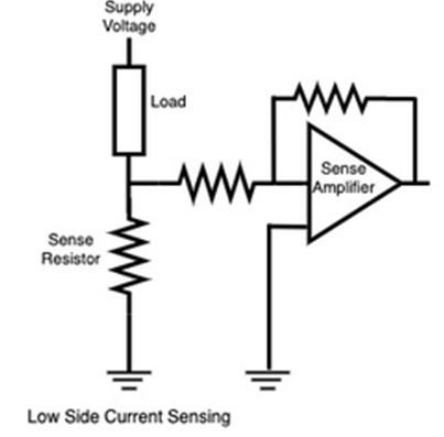
PDF Current Sensing Circuit Concepts and Fundamentals As shown in Figure 1, low-side current sensing connects the sensing resistor between the load and ground. Normally, the sensed voltage signal (VSEN=ISEN × RSEN) is so small that it needs to be amplified by subsequent op amp circuits (e.g., non- inverting amplifier) to get the measurable output voltage (VOUT). FIGURE 1:Low-Side Current Sensing.
FAQ - Functional Devices, Inc.
Relay Wiring Diagram: A Complete Tutorial | EdrawMax The diagram above is the 5 pin relay wiring diagram. There are different kinds of relays for different purposes. It can be used for various switching. Relay can be the best option to control electrical devices automatically. 5 pin is compromised of 3 main pins and an SPDT (single pole double throw).

AN-105: Current Sense Circuit Collection Making Sense of ...
Current Sensing Techniques - Circuit Digest During the current sensing process, the current is measured by measuring the magnetic field. The output voltage is very low and needs to be amplified to a useful value by using a high gain amplifier with very low noise. Apart from amplifier circuit Hall Effect sensor requires additional circuitry as it is a linear transducer. Pros:

Low Current Triggered Relay | Circuit Diagram
How to Build a Current Sensor Circuit For this circuit, we will select the Vishay WSLP59312L000FEA current sense resistor. This is a 2 mOhm, 8W, 1% tolerance current sense resistor. Let's say we are working with a battery management system that is designed for a maximum of 62.5A. Doing the math, Power= I 2 R= 7.8125W
Switch Output Voltage Sensor Current Sensing Relay Current Sensor Module - Buy Current Sensor Module,Current Sensing Relay,Voltage Sensor Product on ...
AN-105: Current Sense Circuit Collection Making Sense of ... The upper circuit (a) uses an instrumentation amplifier (IA) powered by a separate rail (>1V above V IN) to measure across the 1kΩ current shunt. The lower figure (b) is similar but derives its power supply from the APD bias line. The limitation of these circuits is the 35V maximum APD voltage, whereas some APDs may require 90V or more.
Using Sensor Data to Activate a 5V Relay on the Arduino ...
How to Set Up a 5V Relay on the Arduino - Circuit Basics 2015-11-28 · One of the most useful things you can do with an Arduino is control higher voltage (120-240V) devices like fans, lights, heaters, and other household appliances. Since the Arduino operates at 5V it can’t control these higher voltage devices directly, but you can use a 5V relay to switch the 120-240V current and use the Arduino to control the relay.

HVAC Current Sensing Relay Operation and Troubleshooting!
Current Sensor Relays - Grainger Industrial Supply Current sensor relays detect voltage changes and switch power on or off. They protect heavy machinery from damage from overloads, undercurrents, and lamp loads. Note: Product availability is real-time basis and adjusted continuously. The product will be reserved for you when you complete your order.
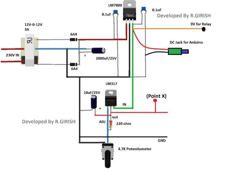
Over Current Cut-off Power Supply Using Arduino - Homemade ...
Current Sensing Circuit : 5 Steps - Instructables Ways to measure current: 1- Indirect method: such as current transformers (in the figure) and Hall effect sensors, which relies on Faraday's law of induction to sense current in a circuit and convert it to a proportional voltage. These methods are suitable more for high current systems. 2- Direct method: which relies on Ohm's law which states that V = I x R.

Residual current device (RCD) protecting a 3-phase circuit; e ...
Voltage Sensor Circuit - isolated voltage sensor power ... Voltage Sensor Circuit - 16 images - results page 2 about sensors searching circuits at, hev tv 1 7 high voltage battery pack temp sensors youtube, what are different types of sensors with circuits, p0641 sensor reference voltage a circuit open,

Relay Switch Circuit and Relay Switching Circuit
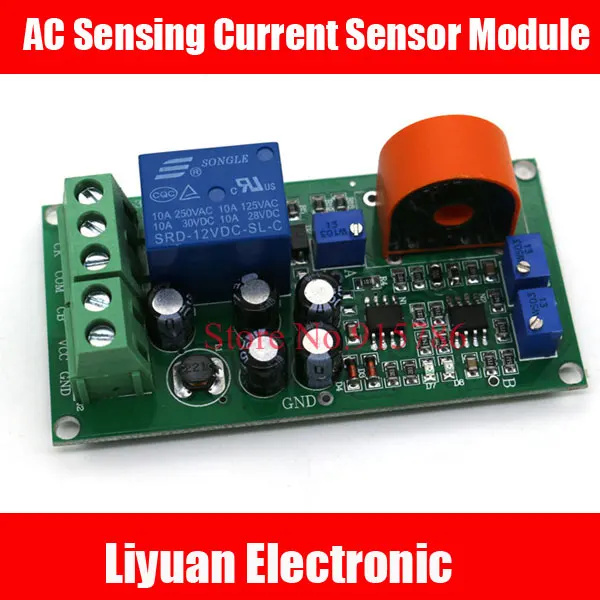
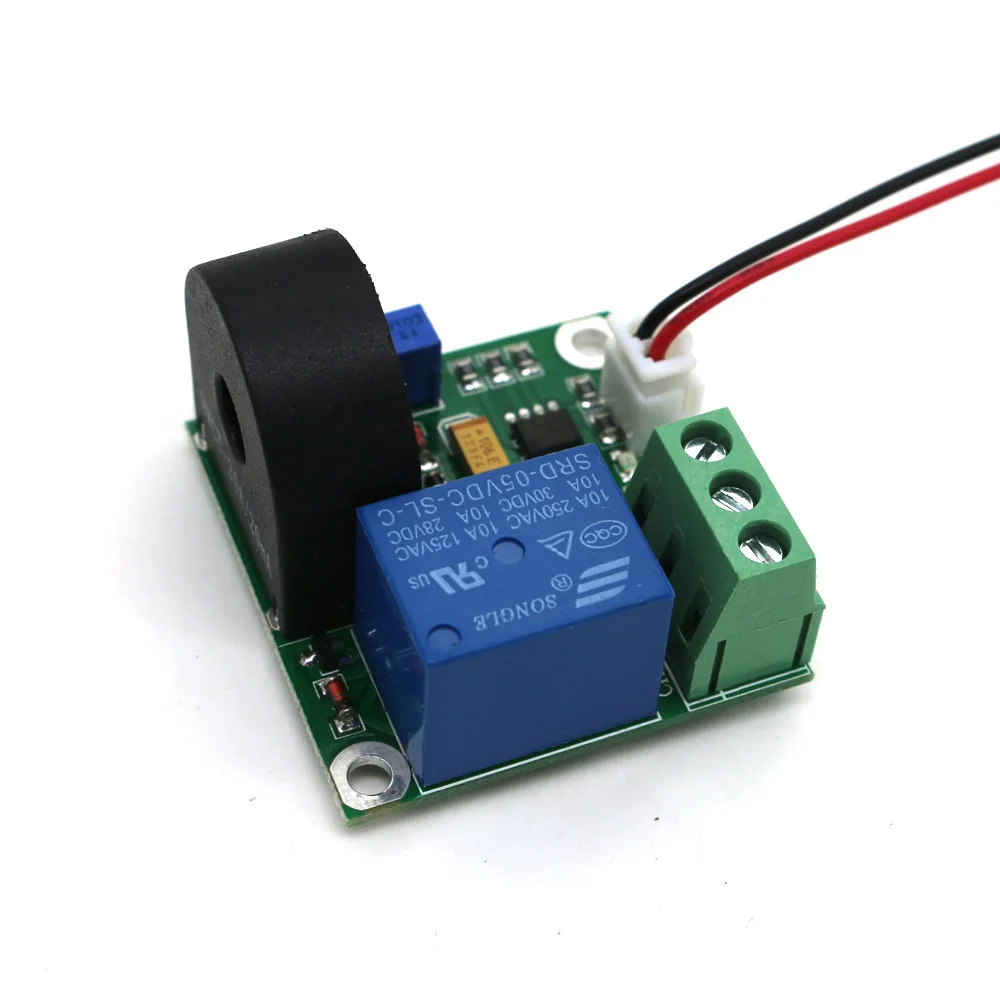
AC Sensing Current Sensor Module / 0-5A Adjustable Relay Output Current Module / Full Range Linear Current Sense Module

Current Sensor ACS712 Pin and Working Details - Androiderode

Schematic overview of the high-current DC current ratio ...
Current sensor switch circuit - Gadgetronicx
Current Transformer Electronics Relay Wiring Diagram, PNG ...
Current activated switch - DIYWiki

Undervoltage Relay Connection Diagram and Wiring Procedure ...
Linear Hall-Effect Sensor - Working and Application Circuit ...

COMBINATION CURRENT SENSOR AND RELAY - diagram, schematic ...
The Basics of Current-Sensing Relays | EC&M

Clear Glass Sensor

AN-105: Current Sense Circuit Collection Making Sense of ...

Current Sensor Circuit. | Download Scientific Diagram

Amazon.com: Current Sensing Switch, Normally Open Current ...
Precision Current Sensing and Monitoring Circuit using IC ...
Results page 313, about 'Stereo PLL AM transmitter ...

How To Hook Up a Digital Magnetic Sensor to a Relay | Sensor ...

Current sensor circuit diagram | Download Scientific Diagram

Relay Current Flow & Wiring Diagrams
0 Response to "39 current sensing relay circuit diagram"
Post a Comment