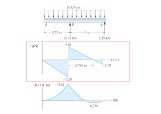
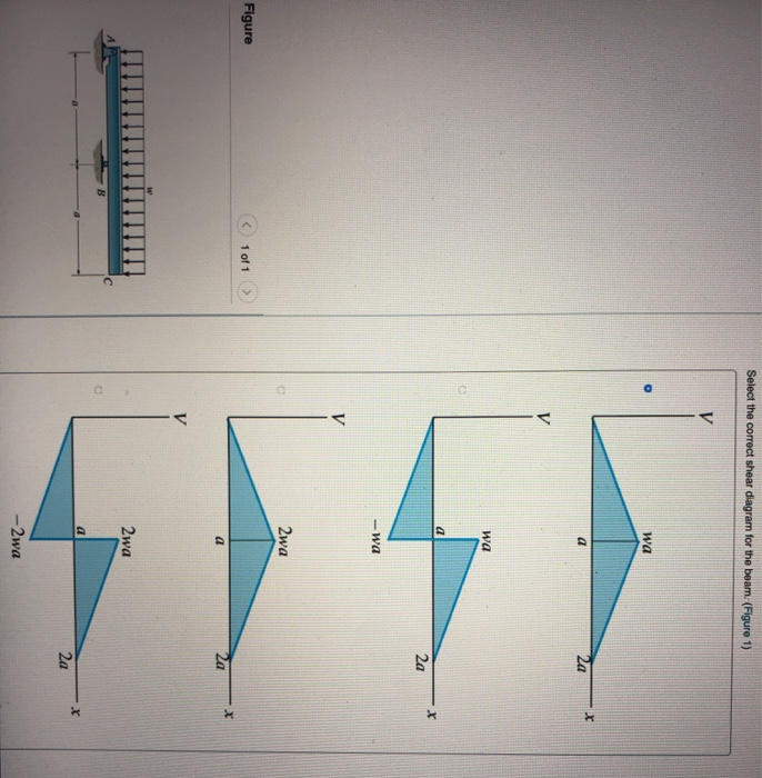
40 select the correct shear diagram for the beam.
MEGR 2144 Final Flashcards | Quizlet Please select right diagram forms for the shear force and bending moment for the beam in the Figure. constant. If the distributed load q on a beam is 0, the shear force V is ... The normal stresses of a beam under pure bending (check all correct answers) m^4 in^4. The moment of inertia of the cross-sectional area of a beam has the following SI ... Consider a beam shown in the figure below. (Figure 1) ? Part Consider a beam shown in the figure below. (Figure 1) ? Part A Draw the shear diagram for the beam Click on "add vertical line off" to add discontinuity lines. Then click on "add segment" button to add functions between the lines Note Make sure you place only one vertical line at places that require a vertical line.
Bending moments and shear force | Physics Quiz - Quizizz Preview (7 questions) Show answers. Select the correct shear force diagram to match this bending moment diagram: Select the correct statement regarding the bending moment diagram: There are two point loads. There are three point loads. There is a uniform distributed load as well as point loads. The beam is hogging.

Select the correct shear diagram for the beam.
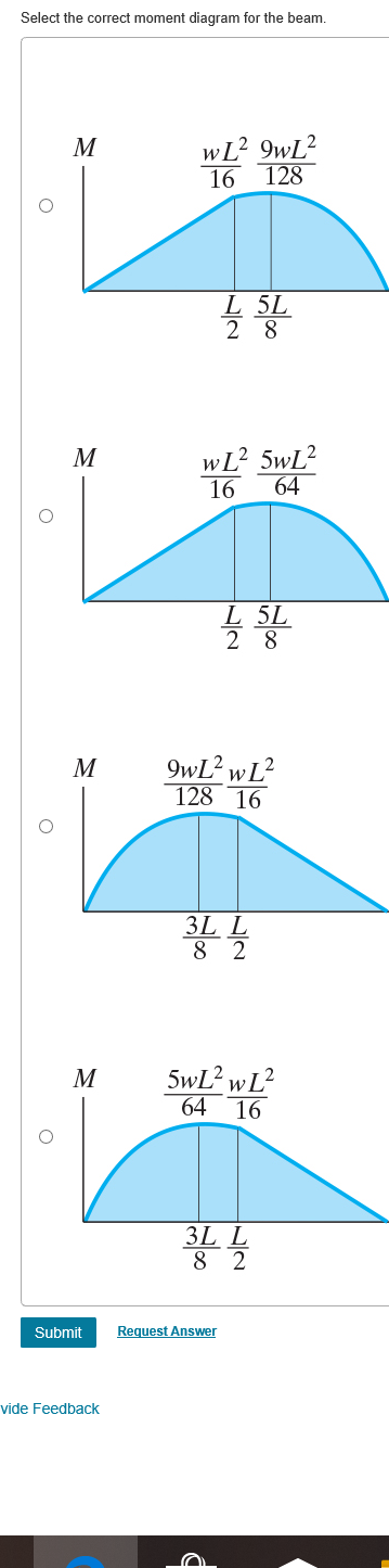
Structural Steel - Metal Supermarkets 21.02.2015 · Structural Beam. Structural Beams come in various shapes and sizes so it is important to use the correct terminology when measuring. Beam Terms. Beam Depth: The distance from the top and bottom surface of the steel (see “A” in diagram). Flange Width: The top and bottom flat horizontal sections width (“B”). The Ultimate Guide to Shear and Moment Diagrams ... After completing this course… You will be fully competent in drawing shear force and bending moment diagrams for statically determinate beams and frames.; You will have a robust system of analysis that allows you to confidently tackle the analysis of any statically determinate structure.; You will understand the relationship between external loading and the shear forces and bending moments ... Solved Part A Select the correct shear diagram for the ... Expert Answer 100% (5 ratings) Transcribed image text: Part A Select the correct shear diagram for the beam (Figure 1) V WL * 5L 8 L WL 4 V WL 뿡 X ЗwL. 8 V WL 8 3L 8 WI V wL 8 3L 8 X Figure 3wL 8 Submit Request Answer Part B Select the correct moment diagram for the team Previous question Next question
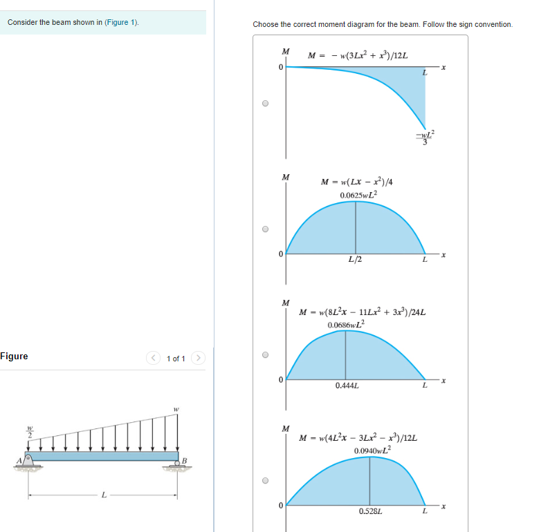
Select the correct shear diagram for the beam.. Answered: 10/10 FOR THE BEAM SHOWN IN FIGURE.… | bartleby solution for 10/10 for the beam shown in figure. choose the correct bending moment diagram 1 kn/m a. 2 m 2 m 2 m PDF Chapter 4 Shear and Moment In Beams - ncyu.edu.tw The simply supported beam in Fig. (a) is loaded by the clockwise couple C 0at B. (1) Derive the shear and bending moment equations. And (2) draw the shear force and bending moment diagrams. Neglect the weight of the beam. The support reactions A and C have been computed, and their values are shown in Fig. (a). Solution Part 1 PDF Beam Design Formulas With Shear and Moment IntroductionNotations Relative to "Shear and Moment Diagrams" E= modulus of elasticity, psi I= moment of inertia, in.4 L= span length of the bending member, ft. R = span length of the bending member, in. M= maximum bending moment, in.-lbs. P= total concentrated load, lbs. R= reaction load at bearing point, lbs. V= shear force, lbs. Select the correct influence line diagram for shear force ... Maximum shear force isat either of the support due to a point load Select the correct influence line diagram for shear force at x of the following beama)b)c)d)Correct answer is option 'B'. Can you explain this answer? | EduRev Civil Engineering (CE) Question
Answered: Draw the shear diagram for the beam.… | bartleby Draw the shear diagram for the beam. Follow the sign convention. (Figure 1) Click on "add vertical line off" to add discontinuity lines. Then click on "add segment" button to add functions between the lines. Note 1- You should not draw an "extra" discontinuity line at the point where the curve passes the x-axis. PDF Shear Forces and Bending Moments in Beams Shear and Bending Moment Diagrams: The loading on most beams is such that the stress resultant on planes perpendicular to the axis of the beam consists of a shear force, V, and a bending moment, M. In determining beam responses, it is very convenient, if not essential, to first determine the shear and bending moment diagrams. 163 questions with answers in ETABS | Science topic 14.04.2022 · I am trying to model the shear link in sap2000/ etabs by I do not know how to model the web stiffened beam in this software because for the shear link we have to use web stiffness. Please suggest ... 5 Best Free Bridge Design Software For Windows The analysis report basically displays the suggestions to correct your design if it is unstable. You can also view analysis reports such as Load Test Results, Cost Calculations Report, Shear Diagram and Moment Diagram, Concrete Properties, Cross Beam Analysis Result, Cross Beam Live Load Result, Deflection History, Effective Prestress, Girder Properties, Girder Stability, …
Modelling and analysis - SteelConstruction.info Concrete shear walls which are typically planar elements or groups of planar elements (cores) which resist the lateral load in shear or shear and bending respectively. Model of a multi-storey building (Image courtesy of Trimble Solutions (UK) Ltd.) A number of simplifying assumptions are made when modelling the building for analysis: Analysis elements are aligned with the tops of … FE Civil Practice Problems - PrepFE In this particular example, this beam loading-support condition is not part of the table. Therefore, we have no alternative but to use shear and moment diagrams to determine the maximum bending moment in the beam. Steps to draw shear and moment diagrams: 1. Draw a free body diagram of the beam. 2. Determine all the reactions and moments by ... Draw The Shear And Moment Diagram For Cantilever Beam ... Draw The Shear Force And Bending Moment Diagrams For A Cantilever Beam Ab Acted Upon By Two Diffe Load Cases Distributed With Li Variation Maximum Intensity Q O See Figure P. Solved Express The Internal Shear And Moment In Cantilevered Beam As 1 Transtutors. Shear Force Bending Moment Diagram Exchange Pick Of The Week Matlab Simulink. Select the correct shear and bending- moment diagrams for ... Select the correct shear and bending- moment diagrams for the beam and loading shown, and determine the maximum absolute value (a) of shear, (b) of the bending moment. Engineering & Technology Mechanical Engineering NUCL 27300 Answer & Explanation Unlock full access to Course Hero Explore over 16 million step-by-step answers from our library
For the beam and loading shown, (a) select the correct shear ...
Part A Consider the beam shown in (Figure 1 ... - Wegglab Part A Consider the beam shown in (Figure 1). Follow the sign convention. Draw the shear diagram for the beam Click on "add vertical line off" to add discontinuity lines. Then click on "add segment" button to add functions between the lines. Note 1-You should not draw an "extra" discontinuity line at the point where the curve passes ...
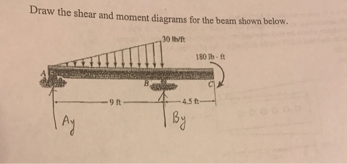
Solved) - Draw the shear and moment diagrams for the beam ...
Statics: Free Body Diagrams - Engineering Statics Select a reference frame. Select a right-handed coordinate system to use as a reference for your equilibrium equations. If you are using something other than a horizontal \(x\) axis and vertical \(y\) axis, indicate it on your diagram. Look ahead and select a coordinate system which minimizes the number of unknown force components in your ...
Can you draw the shear force and bending moment diagrams of ...
(PDF) Structural Analysis by R C Hibbeler ... - Academia.edu Academia.edu is a platform for academics to share research papers.
Solved Choose the correct shear diagram for the beam. Follow ...
Joist Hangers & Post & Beam Framing Connectors; Guide to ... You can select the connector based on simple framing descriptions: You want a Post to Beam connector that matches a doubled 2x6 (about 3" in width) to a 6x6 post top (about 5.5" square) - you'll see connectors labelled accordingly and easier to …
Solved ▽ Part A Select the correct shear diagram for the ...
Calculating Shear Force Diagram | SkyCiv Engineering Calculating Shear Force Diagram - Step 2: Keep moving across the beam, stopping at every load that acts on the beam. When you get to a load, add to the Shear Force Diagram by the amount of the force. In this case we have come to a negative 20kN force, so we will minus 20kN from the existing 10kN. i.e. 10kN - 20kN = -10kN.
PSL-ЗОНИРОВАНИЕ И ПОДБОР МАТЕРИАЛОВ НАСОСНО- КОМПРЕССОРНЫХ ...
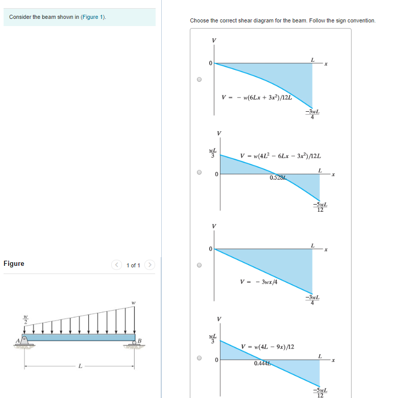
Solved Choose the correct shear diagram for the beam ... View the full answer Transcribed image text: Consider the beam shown in (Figure 1). Choose the correct shear diagram for the beam. Follow the sign convention V - - w (6Lx + 3x)/12L -32 V = w (4L2 - 6Lx - 3x?)/12L 0.528. Figure 1 of 1 > V = - 3wx/4 -32 V = w (4L - 9x)/12 0.4445 Consider the beam shown in (Figure 1).
Solved Choose the correct shear diagram for the beam. Follow ...
PDF 4. Bending Moment and Shear Force Diagram This system will be followed in shear force and bending moment diagram and in deflection of beam. Here downward direction will be negative i.e. negative Y-axis. Therefore downward deflection of the beam will be treated as negative. We use above Co-ordinate system Some books fix a co-ordinate axis as shown in the following figure.

Beam Reactions and Diagrams – Strength of Materials ...
[Solved] The shear-force diagram of a loaded beam is shown ... Download Solution PDF The shear-force diagram of a loaded beam is shown in the following figure. The maximum bending moment in the beam is This question was previously asked in UPPSC AE Mechanical 2013 Official Paper I Attempt Online View all UPPSC AE Papers > 16 kN-m 11 kN-m 28 kN-m 8 kN-m Answer (Detailed Solution Below) Option 1 : 16 kN-m

Please make answers and work legible. also find the absolute ...
Answered: Draw the shear diagram for the beam… | bartleby Draw the shear diagram for the beam Click on "add vertical line ofr to add discontinuity lines. Then click on "add segment" button to add functions between the lines. Note 1- Make sure you place only one vertical line at places that require a vertical line.

ВИССВАСС
Prestressed Concrete Design - SlideShare 10.01.2016 · The cracked shear capacity, cr V , is empirically give by: 1 0.55 0.1ps o cr c v v cu pu f M V v b d V b d f f M ⎛ ⎞ = − + ≥⎜ ⎟⎜ ⎟ ⎝ ⎠ In which: M is the moment acting at the section; V is the shear acting at the section; 0 M is the moment required to remove 0.8 of the compressive stress at the level of the prestress: 0 , 0.8 c e I M f e = where: 2 , s s c e g g P Pe f A I ...

Beam moment and shear force calculations using digital-camera ...
virtual-mode.de Select a type of wood based on your load needs. Design Properties and Layup thick laminations. About span timber Heavy tables beam . 20 Allowable Load (plf) for 3-1/2-inch Wide 24F-V4/DF Glulam Floor Beams - 100% Floor Load Span Treated mechanical beams are constructed based on the required load and span and are composed of layers of Treated timbers or lumber held …

工程力学
Q 1 The bending moment diagram of the beam shown in the ... Q 9 Consider the following statements: A simply-supported beam is subjected to a couple somewhere in the span. It would produce 1. A rectangular SF diagram. 2. Parabolic BM diagrams. 3. Both (+) ve and (-) BMs which are maximum at the point of application of the couple Of these statements a.1, 2, and 3 are correct b.1 and 2 are correct

Select the correct shear and bending moment diagrams
PDF Choose the correct shear diagram Choose the ... - Purdue The beam is subject to the loading shown. 1. Choose the correct shear diagram from the column on the left. 2. Choose the correct moment diagram from the column on the right. Note: The moment diagrams on the right do not necessarily correspond to the diagrams on the left. Circle answers from following choices. Shear diagram Moment diagram 1) a)
Chapter 4-internal loadings developed in structural members
Solved Part A Select the correct shear diagram for the ... Expert Answer 100% (5 ratings) Transcribed image text: Part A Select the correct shear diagram for the beam (Figure 1) V WL * 5L 8 L WL 4 V WL 뿡 X ЗwL. 8 V WL 8 3L 8 WI V wL 8 3L 8 X Figure 3wL 8 Submit Request Answer Part B Select the correct moment diagram for the team Previous question Next question

The simply supported beam is supported by pin support A and ...
The Ultimate Guide to Shear and Moment Diagrams ... After completing this course… You will be fully competent in drawing shear force and bending moment diagrams for statically determinate beams and frames.; You will have a robust system of analysis that allows you to confidently tackle the analysis of any statically determinate structure.; You will understand the relationship between external loading and the shear forces and bending moments ...
Solved Select the correct shear diagram for the beam. | Chegg.com
Structural Steel - Metal Supermarkets 21.02.2015 · Structural Beam. Structural Beams come in various shapes and sizes so it is important to use the correct terminology when measuring. Beam Terms. Beam Depth: The distance from the top and bottom surface of the steel (see “A” in diagram). Flange Width: The top and bottom flat horizontal sections width (“B”).
Mechanics of Materials Chapter 4 Shear and Moment In Beams
Active alignment of receiving beam for coaxial optics in wind ...

A) Draw the shear diagram for the beam. Begin by placing ...
Solved w Jс В Select the correct shear diagram for the ...

Solved) - Draw the shear force and bending moment diagram of ...
5.7 Normal and Shear Stresses | Bending of Beams | InformIT

The correct shear force diagram for the beam shown in the ...

PIC16(L)F19xx Programming Spec Datasheet by Microchip ...

Practice Exams | McGraw-Hill Education - Access Engineering

Solved) - I got part one correct. I just cannot get part 2. I ...

Mastering Engineering, Assignment--12--Beams (Engineering ...
Problem 9.1 Two beam segments, AC and CD, are connected ...
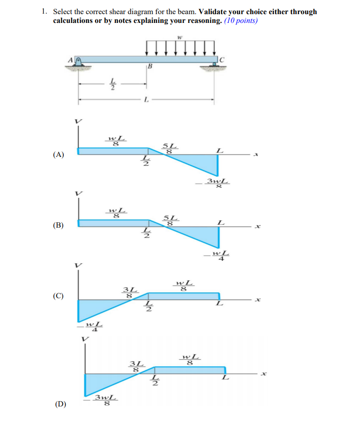
Solved 1. Select the correct shear diagram for the beam ...
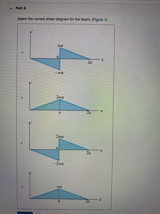
Solved ▽ Part A Select the correct shear diagram for the ...
Fuji Industrial IGBT Module Small Package Solder Pin Type ...
Test: Bending Moment & Shear Force Diagram - 2 | 30 Questions ...
Mechanics of Materials Chapter 4 Shear and Moment In Beams

Mechanism research of slip effect between frictional ...
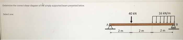
Solved: Determine the correct shear diagram of the simply
1.4: Internal Forces in Beams and Frames - Engineering LibreTexts

A 1 m-long beam has a load of 5 kN applied at its center and ...
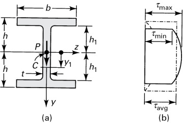
5.7 Normal and Shear Stresses | Bending of Beams | InformIT
Can you draw the shear force and bending moment diagrams of ...

Drawing Shear and Moment Diagrams for Beam
0 Response to "40 select the correct shear diagram for the beam."
Post a Comment