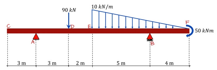
38 draw the shear diagram for the beam.
05.03.2021 · Draw the shear force and bending moment diagrams for the frame subjected to the loads shown in Figure 4.10a. Fig. 4.10. Frame. Solution. Free-body diagram. The free-body diagram of the beam is shown in Figure 4.10a. Support reactions. The reactions at the support of the beam can be computed as follows when considering the free-body diagram and using the equations of equilibrium: … Transcribed image text: Problem 7.70 Draw the shear diagram for the beam. Follow the sign convention. (Figure 1) Click on "add vertical line off" to add ...
A Cantilever Beam Ab Supports Couple And Concentrated Load As Shown In The Figure Draw Shear Force Bending Moment Diagrams For This Bartleby. Draw The Shear Force And Bending Moment Diagrams For A Cantilever Beam Ab Carrying Uniform Load Of Intensity Q Over One Half Its Length See Figure Bartleby. Solved Express The Internal Shear And Moment In ...

Draw the shear diagram for the beam.
a beam. The moment diagram can also be used to predict the qualitative shape of the deflected axis of a beam. General Guidelines on Construction of SFD and BMD Before we go on to solving problems, several standard procedures (or practices) in relation with construction of shear force and bending moment diagrams need to be noted. 1) The load, shear and bending moment diagrams should be ... Compute shear force on the beam by using equation or draw shear diagram: Figure-3: Shear Force Diagram. Shear force at the face of support is 411 KN. However, for simply supported beam, the location of the critical section for shear design is at distance (d), where (d) is effective depth. So, shear force at a critical section of the beam is computed as follow: V u, at distance (d) = (411*(3-0 ... Draw the shear diagram for the beam shown in the figure. Point Load. The load that has an influence only on a single point where it is acting on the beam is known as the point load, The magnitude ...
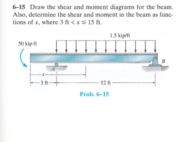
Draw the shear diagram for the beam.. Shear Diagram. The shear at end A is −2 kN. This value is plotted at x = 0, Fig. 6–15 c . Notice how the shear diagram is constructed by following the slopes defined by the loading w . The shear at x = 4 m is −5 kN, the reaction on the beam. This value can be verified by finding the area under the distributed loading, Question: Draw Shear Moment Diagram for the beam loaded as shown. 15 kN 10 kN/m 20 kNm B 2 m -1 m-+ 1 m 2 m V(x) Х M(x) Х Step 1. Given: Step 2. Find: Step 3. Draw Free Body Diagram Step 4. Find Reactions at A and B Step 5. Draw Shear Diagram for all sections using w(x) = . dv/dx Step 6. Draw Moment Diagram for all sections V=dM/dx Draw the moment diagram for the beam. add vertical line off V(lb 1,000 750 500 250 250 -500 750 1,000. Show transcribed image text. Expert Answer. Part A Draw the shear diagram for the beam. Click on "add vertical line off" to add discontinuity lines. Then click on "add segment" button to add functions between the lines. Be sure to indicate the correct types of the functions between the lines, e.g. if in your answer the type of a function is "linear increasing slope" for the function that ...
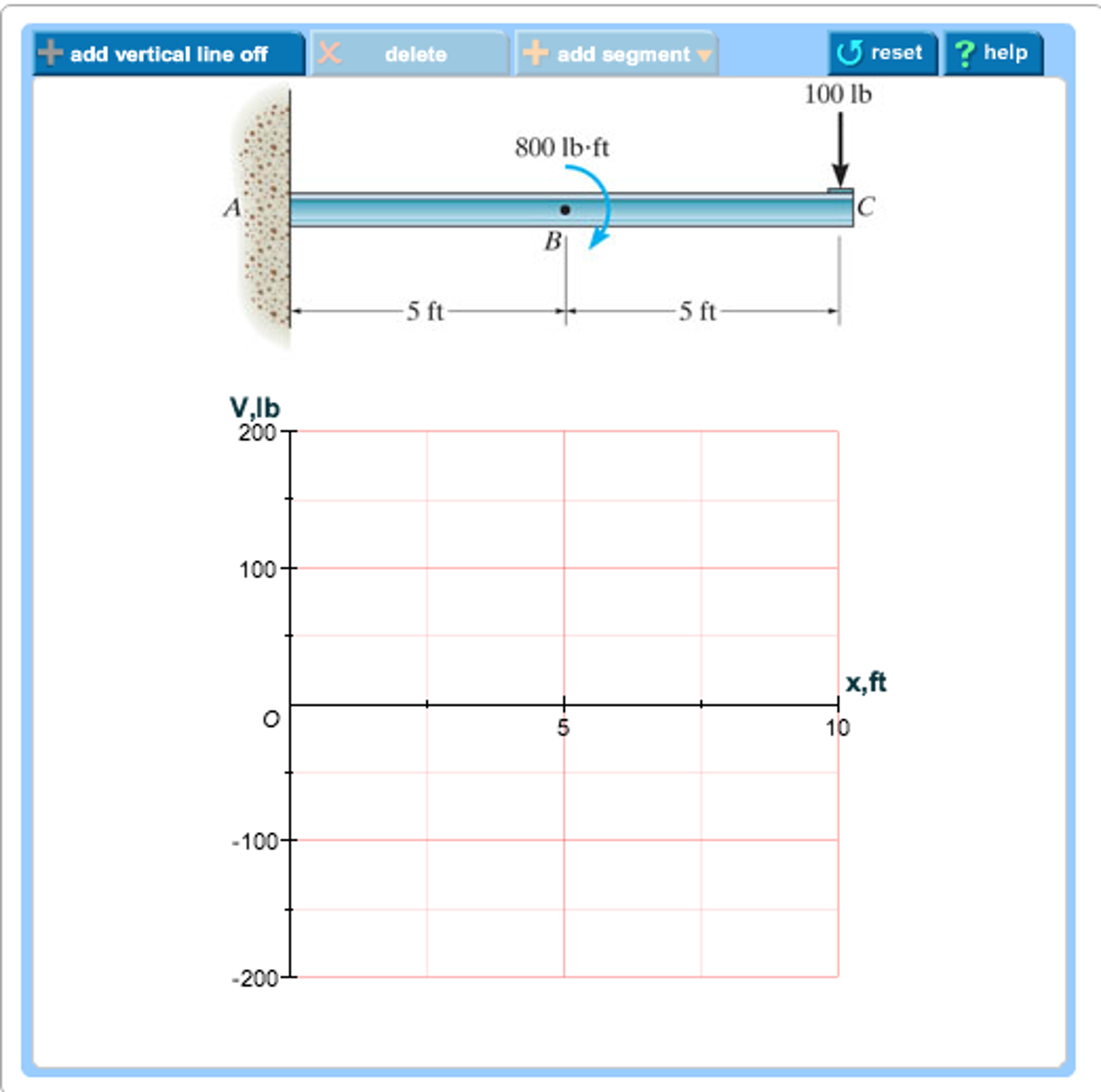
Chapter-4 Bending Moment and Shear Force Diagram S K Mondal’s Maximum bending moment, 2 max wL 2 M at fixed end Another way to describe a cantilever beam with uniformly distributed load (UDL) over it’s whole length. (iii) A Cantilever beam loaded as shown below draw its S.F and B.M diagram In the region 0 < x < a (Figure 1) Part B Draw the moment diagram for the beam. Follow the sign convention. This problem has been solved! See the answer ... has a weight of 1200 lb.Draw the shear and moment diagrams of the boom ABC when it is in the horizontal position shown. 3 ft 5 ft B C 4 ft A The free-body diagram of the beam’s right segment sectioned through an arbitrary point shown in Fig. a will be used to write the shear and moment equations of the beam. *6–4. Transcribed image text: Problem 7.53 Part A Draw the shear diagram for the beam Click on "add discontinuity" to add discontinuity lines.
Draw the shear diagram for the beam. Draw the moment diagram for the beam. PLEASE HELP! NOT SURE WHAT I AM DOING WRONG! Image for Draw the shear diagram for ... Shear Diagram. The shear of −2 kN at end A of the beam is plotted at x = 0, Fig. 6–16 c . The slopes are determined from the loading and from this the shear diagram is constructed, as indicated in the figure. In particular, notice the positive jump of 10 kN at x = 4 m due to the force B_y, as indicated in the figure. Moment Diagram. 15:30Question: Draw the shear and moment diagrams for the beam.Problem 7-61 from:Engineering Mechanics ...8 Jul 2021 · Uploaded by Learning by Teaching (1%) b) Draw free body diagram to find the beam reactions. Determine if the structure is structurally determinate or structurally indeterminate. Determine the degree of determinacy (2%) c) Find the reactions. Show all the calculations. Redraw the free body diagram with the true direction of reactions and with their values (4%) d) Draw axial force diagram. (3%) e) Draw shear force diagram. f ...
Drawing Shear Force Bending Moment Diagram File Exchange Pick Of The Week Matlab Simulink
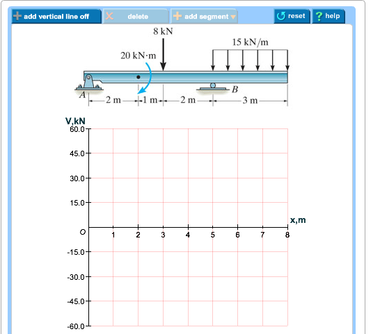
Part A Draw the shear diagram for the beam. Follow the sign convention. (Figure 1) Click on "add vertical line off to add discontinulty lines. Then click on "add segment" button to add functions between the lines. Note 1 - You should not draw an "extra" discontinuity line at the point where the curve passes the x- axis.
The Ultimate Guide To Shear And Moment Diagrams Degreetutors Com
This problem has been solved! Draw the shear diagram for the beam. Draw the moment diagram for the beam. Determine the shear and moment throughout the beam as functions of x for 0 ≤ x ≤ 6ft (Please answer in terms of x) Determine the shear and moment throughout the beam as functions of x for 6ft ≤ x ≤ 9ft.
Hibbeler R C Structural Analysis
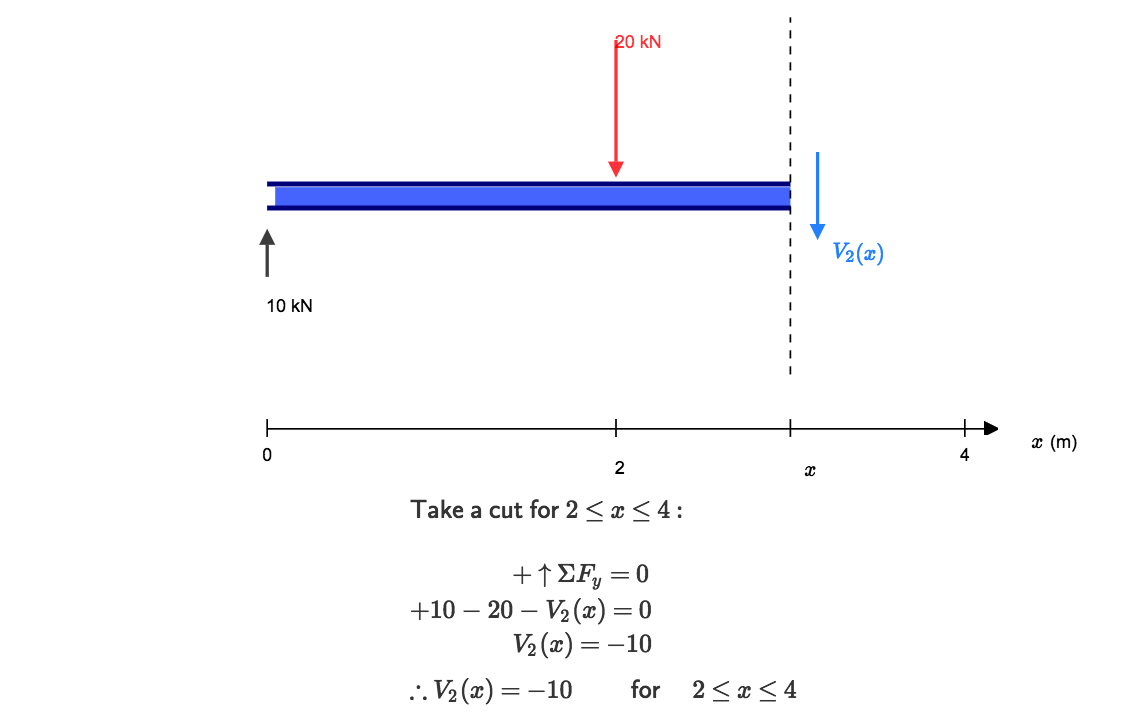
Shear and Moment Functions. Since there is a discontinuity of distributed load and also a concentrated load at the beam’s center, two regions of x must be considered in order to describe the shear and moment functions for the entire beam. M = ( − 2. 5 x 2 2 + 1 5. 7 5 x 2 + 9 2. 5) k N ⋅ m.
Solved Problem 7 48 Part A Draw The Shear Diagram For Chegg Com
Question: 7.78 Draw the shear and moment diagram for the beam. This problem has been solved! See the answer ...

Draw The Shear Diagram For The Beam Follow The Sign Convention Study Com
Transcribed image text: Part A Draw the shear diagram for the beam. Follow the sign convention Click on "add vertical line off" to add discontinuity lines. Then click on "add segment" button to add functions between the lines, Note 1 - Make sure you place only one vertical line at places that require a vertical line.
Draw The Shear Diagram For The Beam Draw The Moment Diagram For The Beam Home Work Help Learn Cbse Forum
Once the loading scenarios are determined, we can draw shear and moment load diagrams for a beam under each scenario. For example, if we know the load for a beam, but its location is uncer-tain, then for one scenario we would locate the load to achieve a maximum moment; for the other we would locate it to achieve maximum shear. Let’s say a ...
1
The reactions have been determined as shown on the beam’s free-body diagram, Fig. 6–6 b . Shear and Moment Functions. A free-body diagram of the left segment is shown in Fig. 6–6 c . As above, the trapezoidal loading is replaced by rectangular and triangular distributions. Note that the intensity of the triangular load at the section is ...

Part A Draw The Shear Diagram For The Beam Part B Draw The Moment Diagram For The Moment Study Com
Transcribed image text: Problem 7.53 Part A Draw the shear diagram for the beam. Click on "add discontinuity" to add discontinuity lines.
Unit 6 Bending Shear And Moment Diagrams Online Presentation
Draw the shear diagram for the beam shown in the figure. Point Load. The load that has an influence only on a single point where it is acting on the beam is known as the point load, The magnitude ...
Solved Draw The Shear And Moment Diagrams For The Beam Figure 1 Draw 1 Answer Transtutors
Compute shear force on the beam by using equation or draw shear diagram: Figure-3: Shear Force Diagram. Shear force at the face of support is 411 KN. However, for simply supported beam, the location of the critical section for shear design is at distance (d), where (d) is effective depth. So, shear force at a critical section of the beam is computed as follow: V u, at distance (d) = (411*(3-0 ...

Drawing Shear And Moment Diagrams For Beam Youtube
a beam. The moment diagram can also be used to predict the qualitative shape of the deflected axis of a beam. General Guidelines on Construction of SFD and BMD Before we go on to solving problems, several standard procedures (or practices) in relation with construction of shear force and bending moment diagrams need to be noted. 1) The load, shear and bending moment diagrams should be ...
Bending Shear And Moment Diagram Graphical Method To Construct Shear Ppt Download

Determine Reactions Draw Shear Bending Moment Diagrams Beams Shown Figs P161 P165 Using Mo Q33066256 Duepapers
Solved Draw Shear Moment Diagrams Beam Also Determine Shear Moment Beam Functions X 3 Ft X Lessth Q20447133 Courseunlock
Calculate And Sketch The Bending Moment And Shearing Force Diagrams For The Horizontal Beam Shown In Figure Sarthaks Econnect Largest Online Education Community
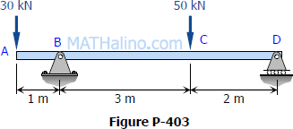
Solution To Problem 403 Shear And Moment Diagrams Strength Of Materials Review At Mathalino
Draw The Shear Diagram For The Beam Draw The Moment Diagram For The Beam Home Work Help Learn Cbse Forum
Solved Draw The Shear Diagram For The Beam Draw The Moment Chegg Com

Draw The Shear And Moment Diagram For The Beam And Loading Shown Study Com
Draw The Shear Diagram For The Beam Wiring Site Resource
4 5 Practice Problems Learn About Structures

Draw The Shear And Moment Diagrams For The Beam With Calculation
Cantilever Beam Shear Force And Bending Moment Diagram Shear And Moment Diagram
Calculations For Shear Force And Bending Moment Diagram For Overhanging Beam

Shear Force And Bending Moment Diagram For Cantilever Beam With Udl Mechanical Engineering Concepts And Principles

4 5 Practice Problems Learn About Structures
Shear And Moment Diagram Wikipedia

Draw The Shear And Moment Diagrams For The Compound Beam Holooly Com

Draw Shear Force And Bending Moment Diagram For Cantilever Beam Bending Moment Shear Force Mathematical Expression
Solved Draw The Shear Force And Bending Moment Diagrams For The Beams 1 Answer Transtutors

Shear And Moment Diagram Wikipedia
Calculating Shear Force Diagrams Skyciv Engineering
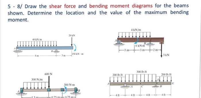
Faculty Kfupm Edu Sa
Chapter 4 Internal Forces In Beams And Frames In Structural Analysis On Manifold Tupress

Beam Reactions And Diagrams Strength Of Materials Supplement For Power Engineering
4 4 Relation Among Distributed Load Shearing Force And Bending Moment Engineering Libretexts
Solved Structural Analysis Drawing Shear And Moment Dia
Solved Draw The Shear Force Bending Moment Diagrams Of The Beam Shown In The Figure Below Taking Into Account The Given Loading Make Detailed Cal Course Hero
0 Response to "38 draw the shear diagram for the beam."
Post a Comment