39 tie lines phase diagram
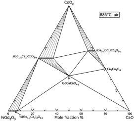
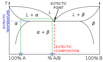
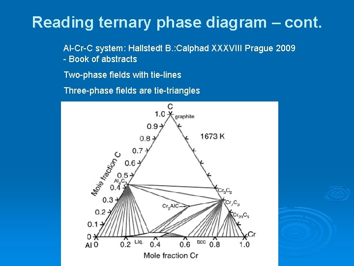
Tie lines in the two-phase areas do not end at a vertical line for a pure solid component as they do in the system shown in the left-hand diagram. The three phases that can coexist at the eutectic temperature of \(\tx{1,052}\K\) are the melt of the eutectic composition and the two solid solutions. The tie lines determined in the two-liquid-phase coexistence region are found to be not parallel, suggesting that the dominant mechanism of lipid phase separation in this region changes with the membrane composition. We provide a phase diagram of the DOPC/eSM/Chol mixture and predict the location of the critical point.
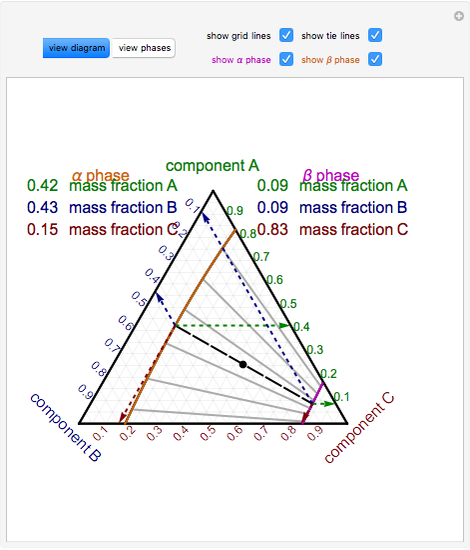
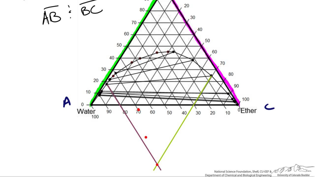
Tie lines connect the compositions of liquid and vapor phases in equilibrium at a fixed pressure. Thus, the ternary phase diagram for CO 2 –C 4 –C 10 mixtures at any pressure is just a constant pressure (horizontal) slice through the triangular prism.
Tie lines phase diagram
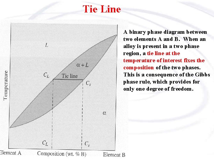
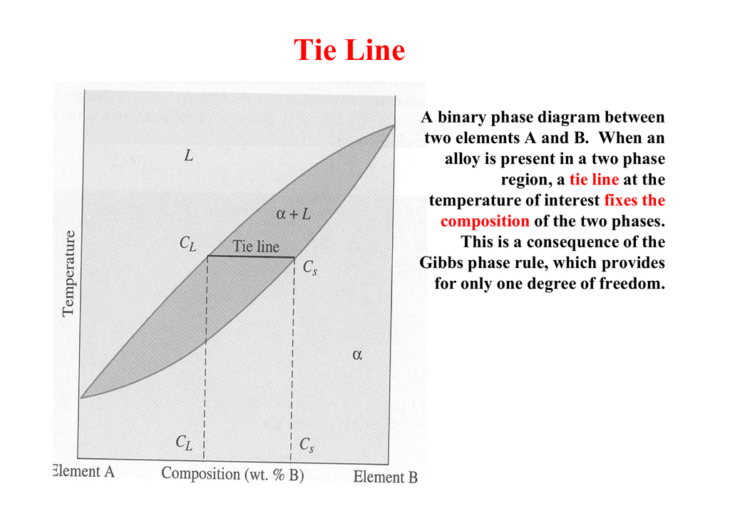
An isothermal (constant temperature) line through the alloy's position on the phase diagram when it is in a two phase field, intersecting the two adjacent solubility curves, is called a tie line (yes, that's the horizontal yellow line on the diagram).. The ends of the tie lines show the compositions of the two phases that exist in equilibrium with each other at this temperature. Three Phase Motor Connection Star/Delta (Y-Δ) Reverse and Forward with Timer Power & Control Diagram As we have already shared the Starting method of Three Phase Motor by Star Delta Starter with Timer Circuit (Power and Control Circuits). Now in the below diagrams, Three phase Motor will rotate in two directions viz Forward and Reverse. This phase diagram consists of two points, two lines and three areas. The two points of the two pure metals A & B. The upper line, obtained by connecting the points showing the beginning of solidification is called liquidius line, and the lower line, determined by connecting the points showing the end of solidification is called the solidus line.
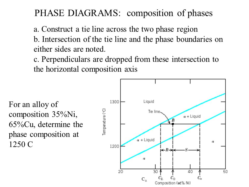
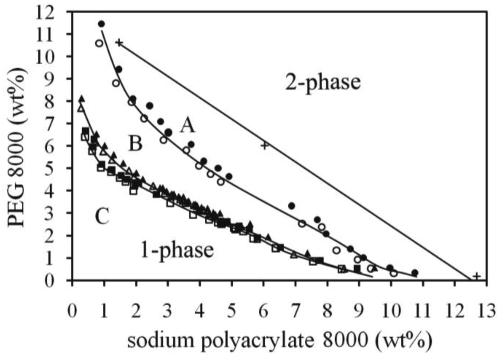
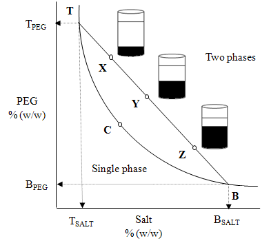
Tie lines phase diagram. 1. Locate composition and temperature in diagram . 2. In two phase region draw the tie line or isotherm . 3. Fraction of a phase is determined by taking the length of the tie line to the phase boundary for the other phase, and dividing by the total length of tie line . The lever rule is a mechanical analogy to the mass balance calculation. The ... mass fraction of each phase is 0.5, estimate: (a) The temperature of the alloy (b) The compositions of the two phases Solution (a) We are given that the mass fractions of α and liquid phases are both 0.5 for a 30 wt% Sn-70 wt% Pb alloy and asked to estimate the temperature of the alloy. Using the appropriate phase diagram, Figure 9.8, by trial Ternary phase diagrams are used to represent all possible mixtures of three solvents [1]; they are described in Chapter 3.Here, we shall indicate how they should be used to minimize the solvent consumption. Figure 2.1 (top) shows the methanol–chloroform–water ternary phase diagram with the tie-lines in the biphasic domain. Five particular compositions are shown in the diagram: Table 2.1 ... The tie lines determined in the two-liquid-phase coexistence region are found to be not parallel, suggesting that the dominant mechanism of lipid phase separation in this region changes with the membrane composition. We provide a phase diagram of the DOPC/eSM/Chol mixture and predict the location of the critical point.
The tie lines determined in the two-liquid-phase coexistence region are found to be not parallel, suggesting that the dominant mechanism of lipid phase separation in this region changes with the membrane composition. We provide a phase diagram of the DOPC/eSM/Chol mixture and predict the location of the critical point. Apr 09, 1997 · Note on Tie Lines. Rarely do you have all the equilibrium tie lines you want. It is thus good to know that there is a fairly easy way of generating additional lines. To do this, you construct a "conjugate curve" from the existing tie lines. Take each endpoint and draw a line from it downward, perpendicular to base of the triangle. in 2-phase region: 1. Draw the tie line. 2. Note where the tie line intersects the liquidus and solidus lines (i.e. where the tie line crosses the phase boundaries). 3. Read off the composition at the boundaries: Liquid is composed of CL amount of Ni (31.5 wt% Ni). Solid is composed of Cαααα amount of Ni (42.5 wt% Ni). The tie lines that connect the ranges for the solid solution compositions are just some of an infinite array of possible tie lines. But, note that a rock with a composition shown as "a" in the diagram, will consist of two phases an X 2 (Z,Y) solid solution and an XYZ solid solution.
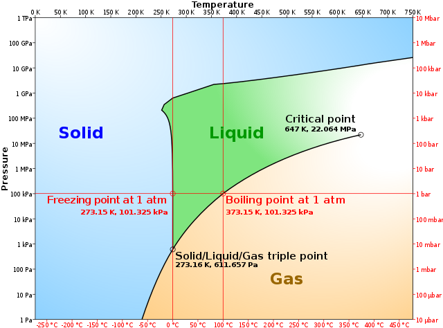
A phase diagram combines plots of pressure versus temperature for the liquid-gas, solid-liquid, and solid-gas phase-transition equilibria of a substance. These diagrams indicate the physical states that exist under specific conditions of pressure and temperature, and also provide the pressure dependence of the phase-transition temperatures ... 1. Locate composition and temperature in diagram 2. In two phase region draw the tie line or isotherm 3. Fraction of a phase is determined by taking the length of the tie line to the phase boundary for the other phase, and dividing by the total length of tie line The lever rule is a mechanical analogy to the mass balance calculation. The simplest phase diagrams are pressure–temperature diagrams of a single simple substance, such as water.The axes correspond to the pressure and temperature.The phase diagram shows, in pressure–temperature space, the lines of equilibrium or phase boundaries between the three phases of solid, liquid, and gas.. The curves on the phase diagram show the points where the free energy (and … This phase diagram consists of two points, two lines and three areas. The two points of the two pure metals A & B. The upper line, obtained by connecting the points showing the beginning of solidification is called liquidius line, and the lower line, determined by connecting the points showing the end of solidification is called the solidus line.
Three Phase Motor Connection Star/Delta (Y-Δ) Reverse and Forward with Timer Power & Control Diagram As we have already shared the Starting method of Three Phase Motor by Star Delta Starter with Timer Circuit (Power and Control Circuits). Now in the below diagrams, Three phase Motor will rotate in two directions viz Forward and Reverse.
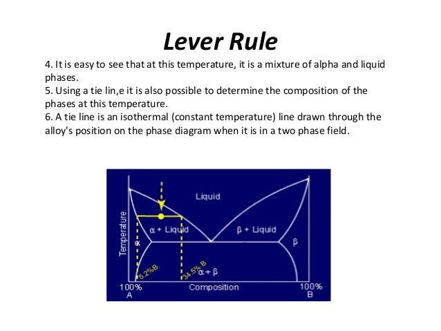
An isothermal (constant temperature) line through the alloy's position on the phase diagram when it is in a two phase field, intersecting the two adjacent solubility curves, is called a tie line (yes, that's the horizontal yellow line on the diagram).. The ends of the tie lines show the compositions of the two phases that exist in equilibrium with each other at this temperature.


0 Response to "39 tie lines phase diagram"
Post a Comment