40 converging lens ray diagram
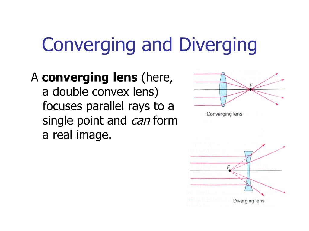
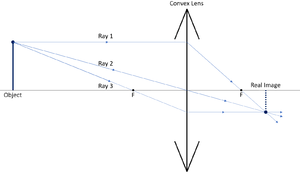
Converging Lens. Diverging Lens. F. Ray 1. F Ray 1. Ray 2. Ray 2. Ray 3 Ray 3. Images’ ’ Tracing Points Draw an arrow to represent the location of an object, then draw any two of the rays from the tip of the arrow. The image is where lines cross. Draw an arrow to represent the location of an Application of converging lens. Trick to drawing ray diagrams for converging lens: There is one ray of light passing through the center of the lens. Always. 2 rays are enough to determine the position of image/object. The other ray of light ALWAYS passes through the focal point of the lens. Either the first focal point of the second focal point.
An object 5 cm in length is held 25 cm away from a converging lens of focal length 10 cm. Draw the ray diagram and find the position, size and the nature of …
Converging lens ray diagram
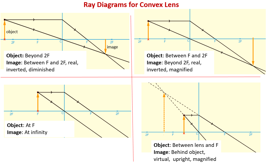
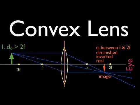
Ray Diagram for Object Located in Front of the Focal Point. In the three cases described above - the case of the object being located beyond 2F, the case of the object being located at 2F, and the case of the object being located between 2F and F - light rays are converging to a point after refracting through the lens. In such cases, a real image is formed. Ray diagram uses lines with arrows to represent the incident ray and the reflected ray. It also helps us trace the direction in which the light travels. Plane Mirror vs Spherical Mirrors . Mirrors are made into different shapes for different purposes. The two of the most prominent types of mirrors are: Plane Mirrors; Spherical Mirrors . A plane mirror is a flat, smooth reflective surface. A ... 26.04.2020 · Concave Lens - Ray diagram. Last updated at April 26, 2020 by Teachoo. For a Concave lens, There are only 2 cases They are Object is Placed at Infinity Object is Placed between Infinity and Optical Center Case 1 - Object is Placed at infinity In this Case, Object is kept far away from mirror (almost at infinite distance) So, we draw rays parallel to principal axis Since ray parallel to ...
Converging lens ray diagram. 5) virtual, inverted, and diminished. Page 7. A real image is formed by a converging lens. If a weak ...15 pages 07.07.2020 · Converging Lens Ray Diagram Virtual Image. Differences Between Converging Lens and Diverging Lens. Converging Lens vs. Diverging Lens: Converging Lens: Diverging Lens: It is thicker at the middle but thinner at the edges: It is thinner at the middle but bulging near the boundaries : It has a focusing action: It diverges a beam of light: It can produce both real and virtual images … The Physics Classroom » Curriculum Corner » Refraction and Lenses » Ray Diagrams for Converging Lenses. The document shown below can be downloaded and printed. Teachers are granted permission to use them freely with their students and to use it as part of their curriculum. Visit the Usage Policy page for additional information. Ray Diagrams for Lenses. The image formed by a single lens can be located and sized with three principal rays. Examples are given for converging and diverging lenses and for the cases where the object is inside and outside the principal focal length. The "three principal rays" which are used for visualizing the image location and size are:
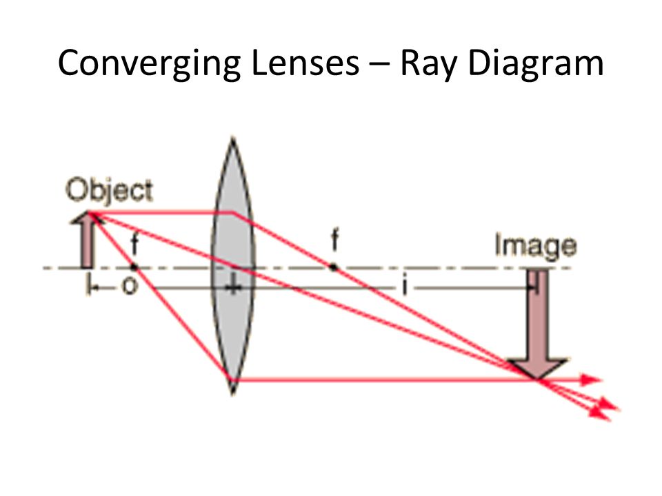
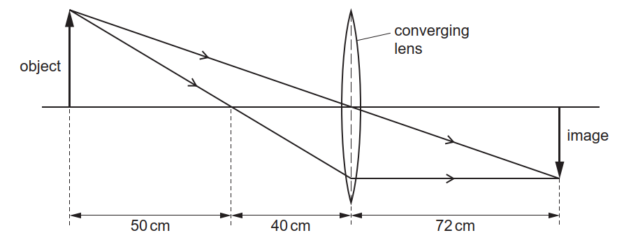
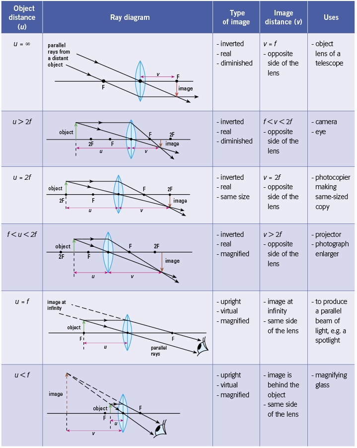
Click here👆to get an answer to your question ️ An object 5 cm in length is held 25 cm away from converging lens of focal length 10 cm . Draw the ray diagram and find the position, size and nature of the image formed. 21.09.2021 · Option C) shows the correct ray diagram.. But why?. First of all, we know that convex lenses are converging lenses. Now, the parallel rays of light originating from the object will undergo refraction from the convex lens and pàss through the focus.; Hence, focal length has been marked. Similarly, the the light rays originating from the object will pàss through the optical centre of the lens ... Here you have the ray diagrams used to find the image position for a converging lens. You can also illustrate the magnification of a lens and the difference between real and virtual images. Ray diagrams are constructed by taking the path of two distinct rays from a single point on the object. A light ray that enters the lens is an incident ray. To explain how to draw the diagrams, there are two key things to remember. 1 A converging lens refracts the light so that any ray of light parallel to the principal axis (the thick horizontal line) is turned to pass through the focal point. Rays of light parallel to the principal axis are all refracted through the focal point.
Description of how to draw ray diagrams for converging lenses for grade 10 science. Diverging Lenses As such, the rules for how light behaves when going through a diverging lens is a little bit different. You will be expected to be able to draw a Ray Diagram of a converging and diverging lens on our upcoming test without the rules. This interactive tutorial utilizes ray traces to explore how images are formed by the three primary types of converging lenses, and the relationship between the object and the image formed by the lens as a function of distance between the object and the focal points. A lens is a transmissive optical device which focuses or disperses a light beam by means of refraction.A simple lens consists of a single piece of transparent material, while a compound lens consists of several simple lenses (elements), usually arranged along a common axis.Lenses are made from materials such as glass or plastic, and are ground and polished or molded to a desired shape.
Convex Lenses And Ray Diagrams Examples Solutions Videos Notes
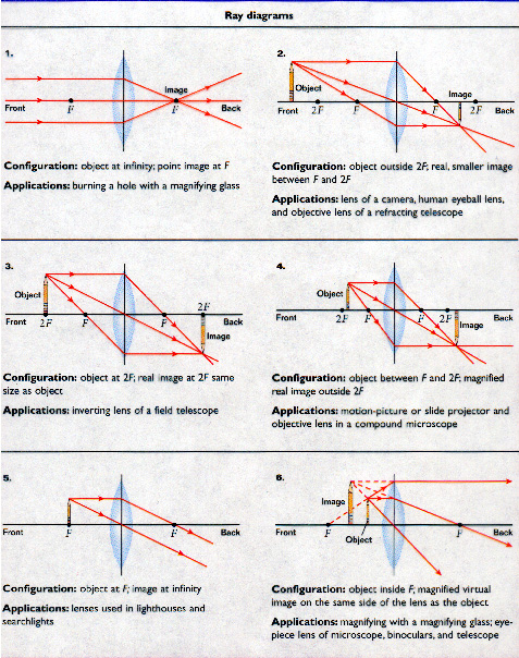
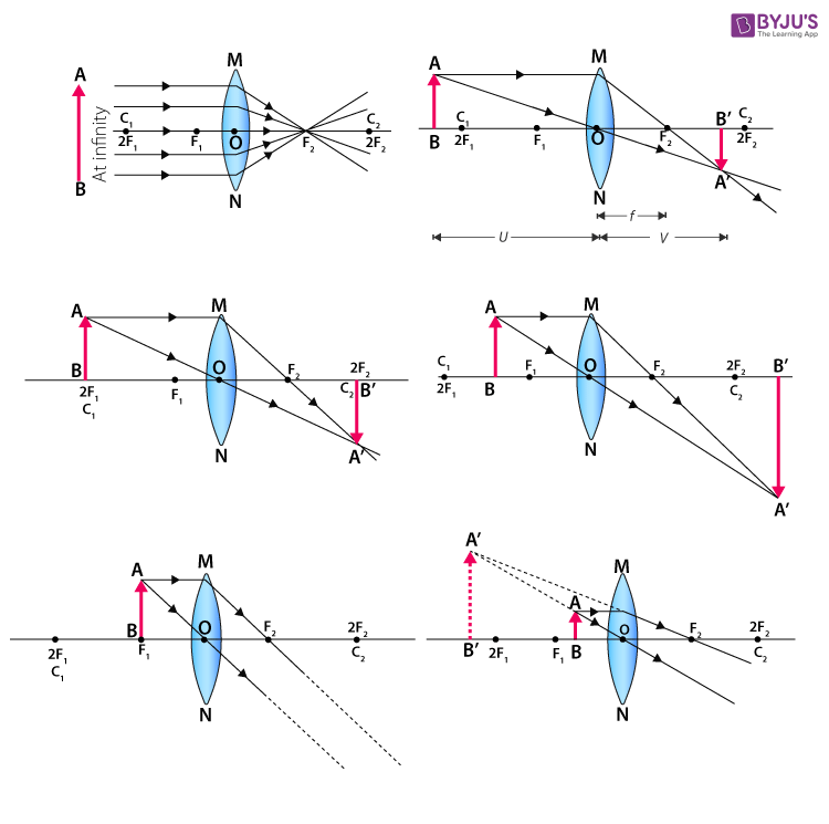
26 Apr 2020 — For a Convex Lens, object can be kept at different positionsHence, we take different casesCase 1 - Object is Placed at infinityIn this Case, ...Position of the object: Position of the imageAt 2F 1 : At 2F 2Beyond 2F 1 : Between F 2 and 2F ...At focus F 1 : At infinity
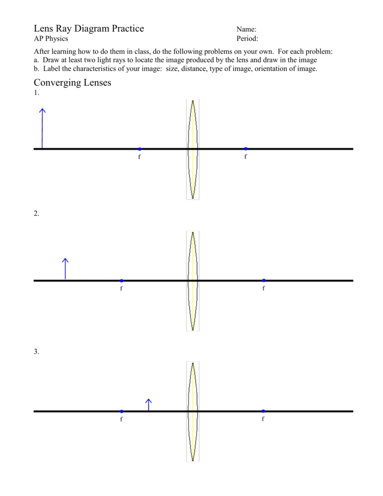
Lens Ray Diagram Practice
The top diagram shows the formation of the virtual object where converging rays are prevented from meeting by the diverging lens. enter image. Any incident ray traveling parallel to the principal axis of a diverging lens will refract through the lens and travel in line with the focal point (i.e., in a direction such.Ray Diagrams for Lenses.
2
26.04.2020 · Concave Lens - Ray diagram. Last updated at April 26, 2020 by Teachoo. For a Concave lens, There are only 2 cases They are Object is Placed at Infinity Object is Placed between Infinity and Optical Center Case 1 - Object is Placed at infinity In this Case, Object is kept far away from mirror (almost at infinite distance) So, we draw rays parallel to principal axis Since ray parallel to ...
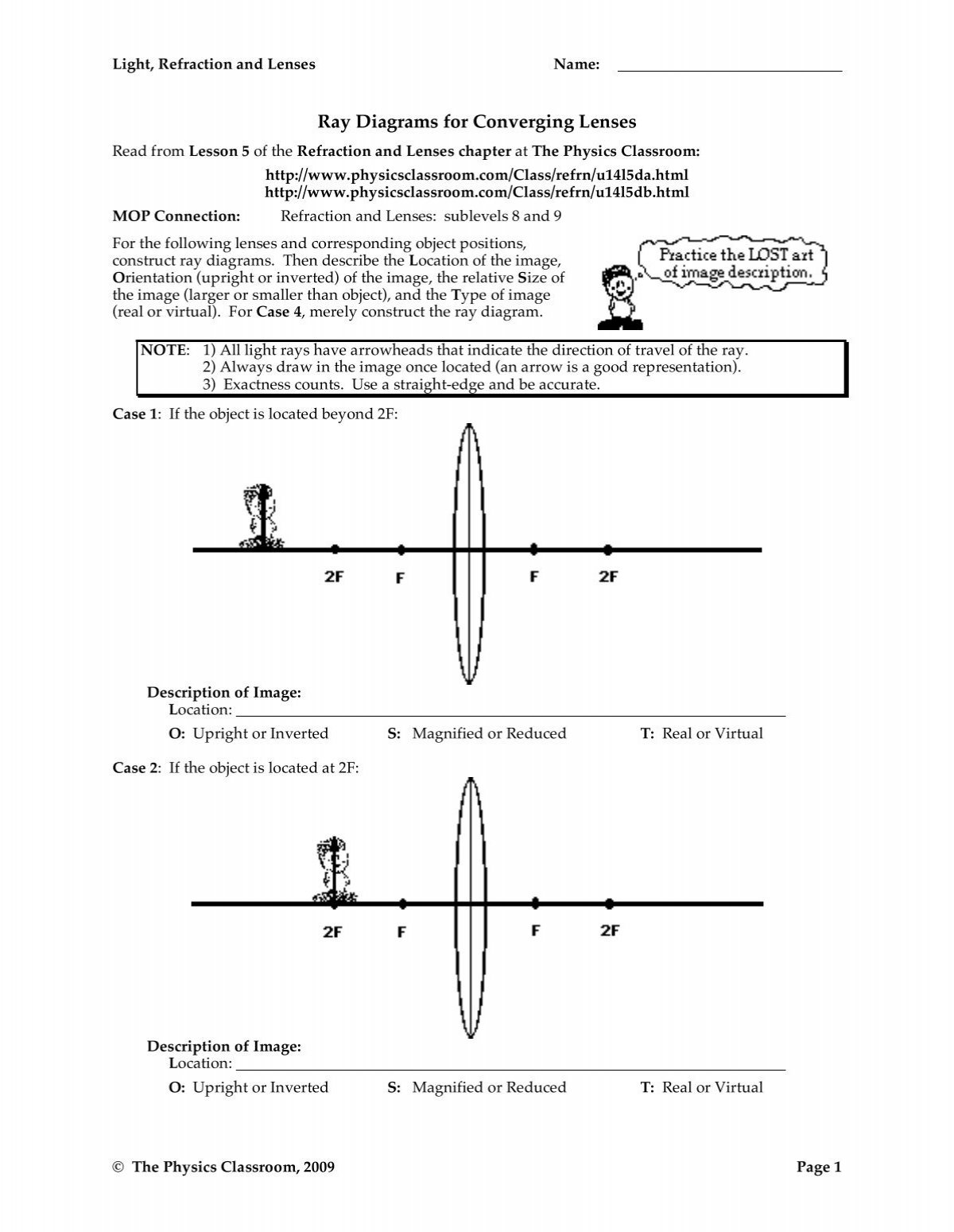
Ray Diagrams For Converging Lenses The Physics Classroom
Ray diagram uses lines with arrows to represent the incident ray and the reflected ray. It also helps us trace the direction in which the light travels. Plane Mirror vs Spherical Mirrors . Mirrors are made into different shapes for different purposes. The two of the most prominent types of mirrors are: Plane Mirrors; Spherical Mirrors . A plane mirror is a flat, smooth reflective surface. A ...

Lenses Convex Lens Ray Diagrams Youtube
Ray Diagram for Object Located in Front of the Focal Point. In the three cases described above - the case of the object being located beyond 2F, the case of the object being located at 2F, and the case of the object being located between 2F and F - light rays are converging to a point after refracting through the lens. In such cases, a real image is formed.

Action Of A Thin Converging Lens Definition Examples Diagrams

Nature Of Images By A Convex And Concave Lenses With Ray Diagrams Definition Examples Diagrams
Ray Diagrams For Lenses

Convex Lens Ray Diagrams Construction Igcse Physics Youtube
Ppt Lenses And Ray Diagrams Powerpoint Presentation Free Download Id 6194668

Ray Diagrams Activity

Image Formation By Convex And Concave Lens Ray Diagrams
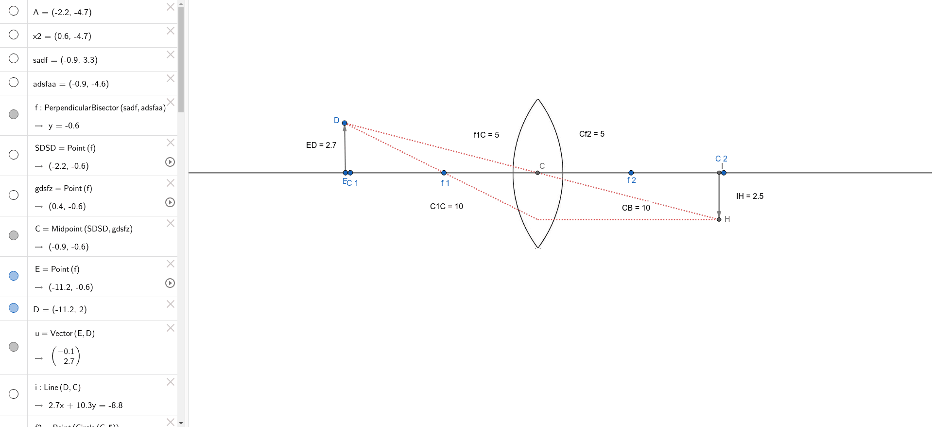
Convex Lens Ray Diagram Geogebra

Figure 8 12 Action Of Lenses Illustrated With Ray Diagrams Optical Tweezers Principles And Applications

Lenses Ray Diagrams For Convex Lenses
Draw A Diagram To Show How A Converging Lens Focuses Parallel Ray Of Light Studyrankersonline

Ejss Model Newtonscadlerealwee

Drawing Ray Diagrams For A Converging Lens The Fizzics Organization
Images Formed By Lenses Ray Diagrams For Lenses Ray Diagrams Can Be Used To Predict Characteristics Of Images Using 3 Rays Just Like For Concave Ppt Download
Lenses Ray Diagram Construction Worksheet Teaching Resources
Physics Tutorial Refraction And The Ray Model Of Light
Ray Diagrams 2 Of 4 Convex Lens Youtube

Pin On Refraction And Lenses
Changing The Way You Learn Quiz

Converging Diverging Lens Ray Diagram Worksheet Pdf

Lens Ray Diagram Worksheet Pdf
Physics Jun Hoe Science Eportfolio
Convex Lens Key Stage Wiki
Word Physics Teacher

The Open Door Web Site Ib Physics Optics Ray Diagrams For Lenses Examples

Convex Lens Concave Lens How To Determine Focal Length Ray Diagrams Image Properties Real Virtual Inverted Size Correction Of Eye Defects Causes Of Long Sight Short Sight Igcse Gcse 9 1 Physics Revision Notes
To Find Image Distance For Varying Distance Of A Concave Lens

Lens Ray Diagram Worksheet Pdf
Solved Convex Lens Ray Diagrams Focal Length Chegg Com
Ss Ray Diagrams For Converging Lens Mini Physics Learn Physics

Which Type Of Lens Is A Converging Lens And Which Is A Diverging Lens Explain Your Answer With Diagrams Flash Education

Terminologies Related To Lens And Rules For Drawing Ray Diagrams Online Science Notes

20140227 Converging Diverging Lens Ray Diagram Worksheet

Lesson Explainer Drawing Ray Diagrams For Convex Lenses Nagwa

1 Principal Ray Diagram For A Thin Converging Lens In This Diagram Download Scientific Diagram
0 Response to "40 converging lens ray diagram"
Post a Comment