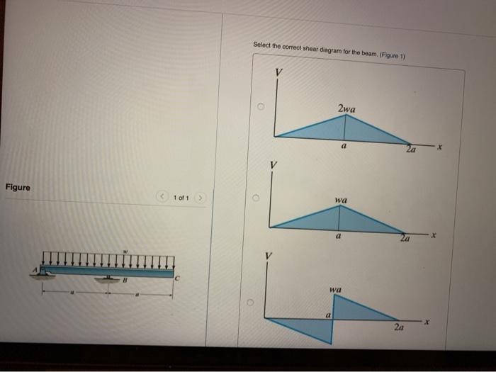
40 select the correct shear diagram for the beam
Draw the moment diagram for the beam. Begin by placing vertical lines. NOTE - The curve you choose from the drop-down is only a pictorial representation of a ... For The Beam And Loading Shown A Select Correct Shear Bending Moment Diagrams B Determine Equations Of Curves Study. Problem 9 1 Two Beam Segments Ac And Cd Are Connected Together At C By A Frictionless Pin Segment Is Cantilevered From R. 329 6 1 Draw The Shear And Moment Diagrams For Shaft Bearings At A B Exert Only Vertical Reactions On.
Nov 24,2021 - Select the correct shear stress distribution diagram for a square beam with a diagonal in a vertical position.a)b)c)d)Correct answer is option ...
Select the correct shear diagram for the beam
Choose the correct shear diagram for the beam. Follow the sign convention. Choose the correct moment diagram for the beam. Follow the sign convention. Show transcribed image text Expert Answer. Who are the experts? Experts are tested by Chegg as specialists in their subject area. We review their content and use your feedback to keep the quality ... beam from the left hand end and summing up the areas of shear force diagrams using proper sign convention. xThe process of obtaining the moment diagram from the shear force diagram by summation is exactly the same as that for drawing shear force diagram from load diagram. Free online beam calculator for generating the reactions, calculating the deflection of a steel or wood beam, drawing the shear and moment diagrams for the beam. This is the free version of our full SkyCiv Beam Software. This can be accessed under any of our Paid Accounts, which also includes a full structural analysis software.
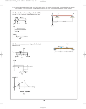
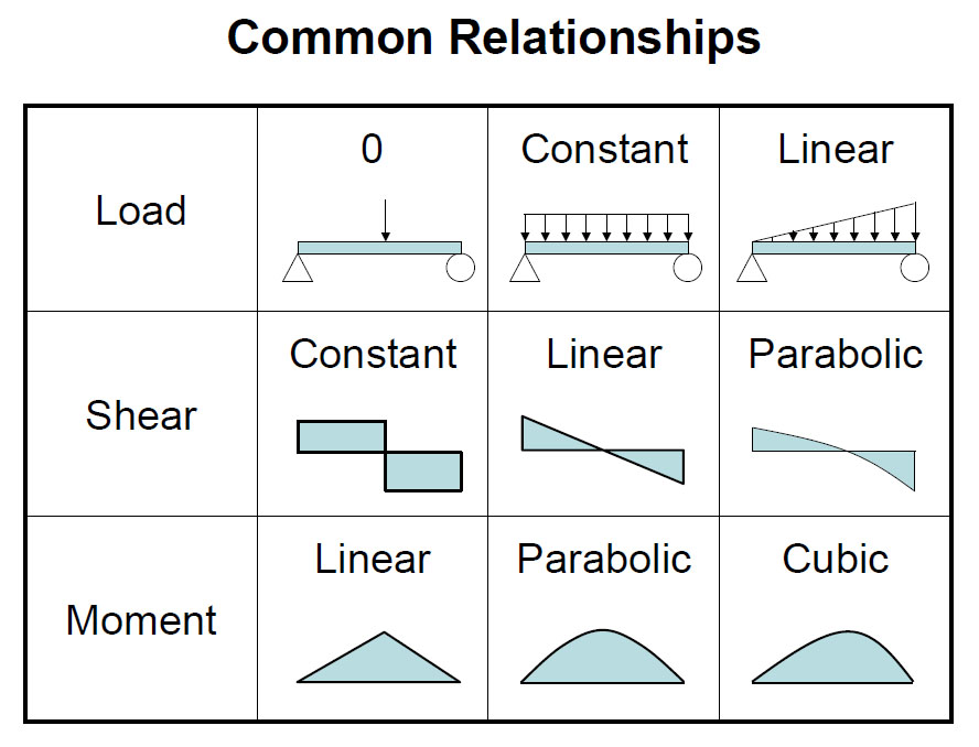
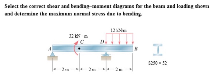
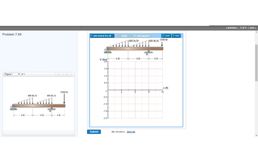
Select the correct shear diagram for the beam. Beams -SFD and BMD V = V 0 + (negative of area under the loading curve from x 0 to x) M = M 0 + (area under the shear diagram from x 0 to x) If there is no externally applied moment M 0 at x 0 = 0, total moment at any section equals the area under the shear diagram up to that section When V passes through zero and is a continuous • A beam is a structural member that is subjected primarily to transverse loads and negligible axial loads. • The transverse loads cause internal shear forces and bending moments in the beams as shown in Figure 1 below. w P V(x) M(x) x w P V(x) M(x) x Figure 1. Internal shear force and bending moment diagrams for transversely loaded beams. This is an example problem that will show you how to graphically draw a shear and moment diagram for a beam. In general the process goes like this:1) Calcul... For the beam and loading shown, (a) select the correct shear and bending-moment diagrams, (b) determine the equations of the shear and bending-moment curves.
Once you have the reactions, draw your Free Body Diagram and Shear Force Diagram underneath the beam. Finally calculating the moments can be done in the following steps: 2. From left to right, make "cuts" before and after each reaction/load. To calculate the bending moment of a beam, we must work in the same way we did for the Shear Force ... When the shear diagram is increasing, the moment diagram is concave upward. When the shear diagram is decreasing, the moment diagram is concave downward. Sign Convention The customary sign conventions for shearing force and bending moment are represented by the figures below. A force that tends to bend the beam downward is said to produce a ... Select the correct shear diagram for the beam figure 1. Solution 43 1 simple beam. This preview has intentionally blurred sections. Shear and bending moment. Shear and bending moment diagrams for beam ab and determine the maximum. As shown in the figure below a uniform beam is supported by a cable at one. desirable to draw the V-diagram below the FBD of the entire beam, and then draw the M-diagrambelow the V-diagram. The bending moment and shear force diagrams of the beam are composites of the V and M diagrams of the segments. These diagrams are usually discontinuous, or have discontinuous slopes.
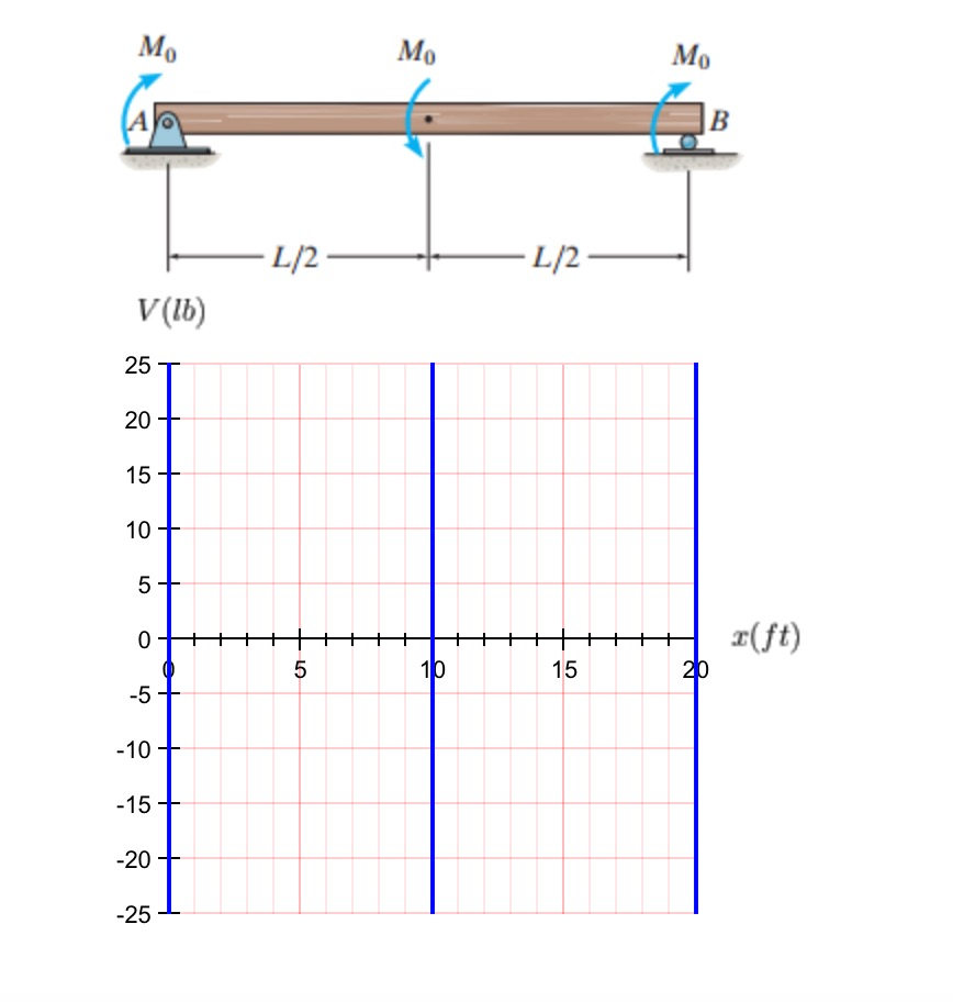
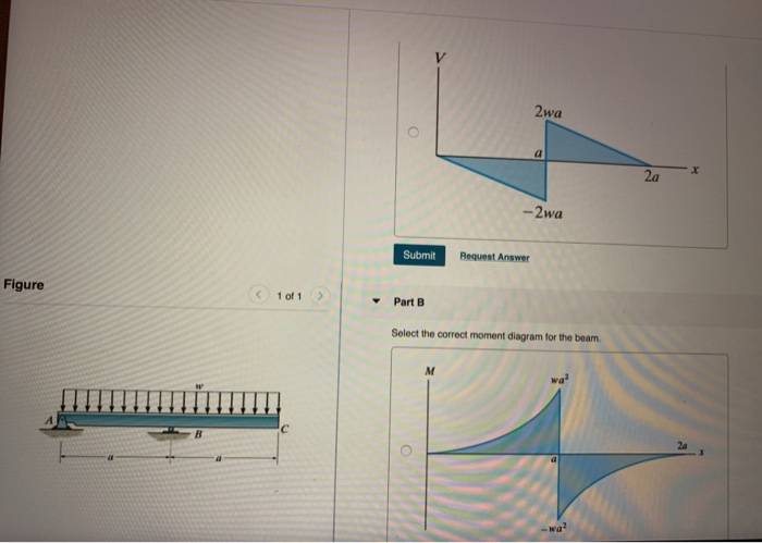
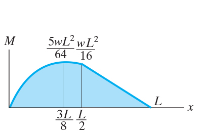
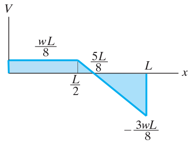
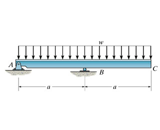
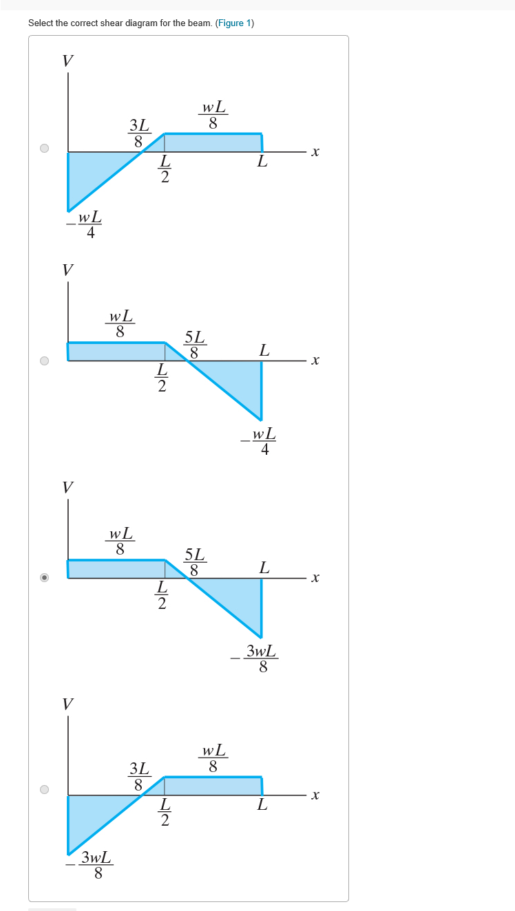
(Figure 1) wa 2a -wa 2wa 2wa x. 2a -2wa wa -Part B Select the correct moment diagram for the beam. 2a 2a 2a 24. This problem has been solved ... a) Calculate the shear force and bending moment for the beam subjected to a concentrated load as shown in the figure. Then, draw the shear force diagram (SFD) and bending moment diagram (BMD). b) If P = 20 kN and L = 6 m, draw the SFD and BMD for the beam. P kN L/2 L/2 A B EXAMPLE 4 Transcribed Image Textfrom this Question. Part A Select the correct shear diagram for the beam (Figure 1) V WL * 5L 8 L WL 4 V WL 뿡 X ЗwL. 8 V WL 8 3L 8 WI V wL 8 3L 8 X Figure 3wL 8 Submit Request Answer Part B Select the correct moment diagram for the team. Shear and moment diagrams and formulas are excerpted from the Western Woods Use Book, 4th edition, and are provided herein as a courtesy of Western Wood Products Association. Introduction Notations Relative to "Shear and Moment Diagrams" E = modulus of elasticity, psi I = moment of inertia, in.4 L = span length of the bending member, ft.
Solved: Draw The Shear Diagram For The Beam. Assume That M ...
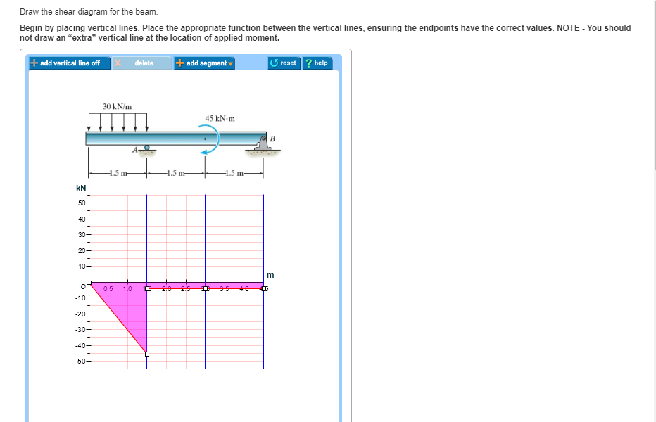
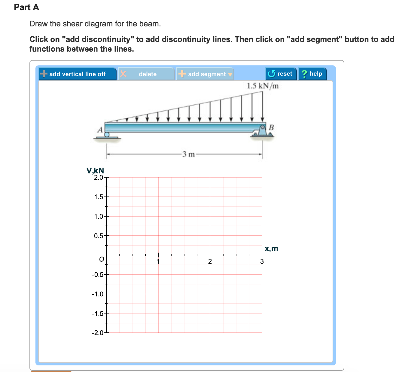
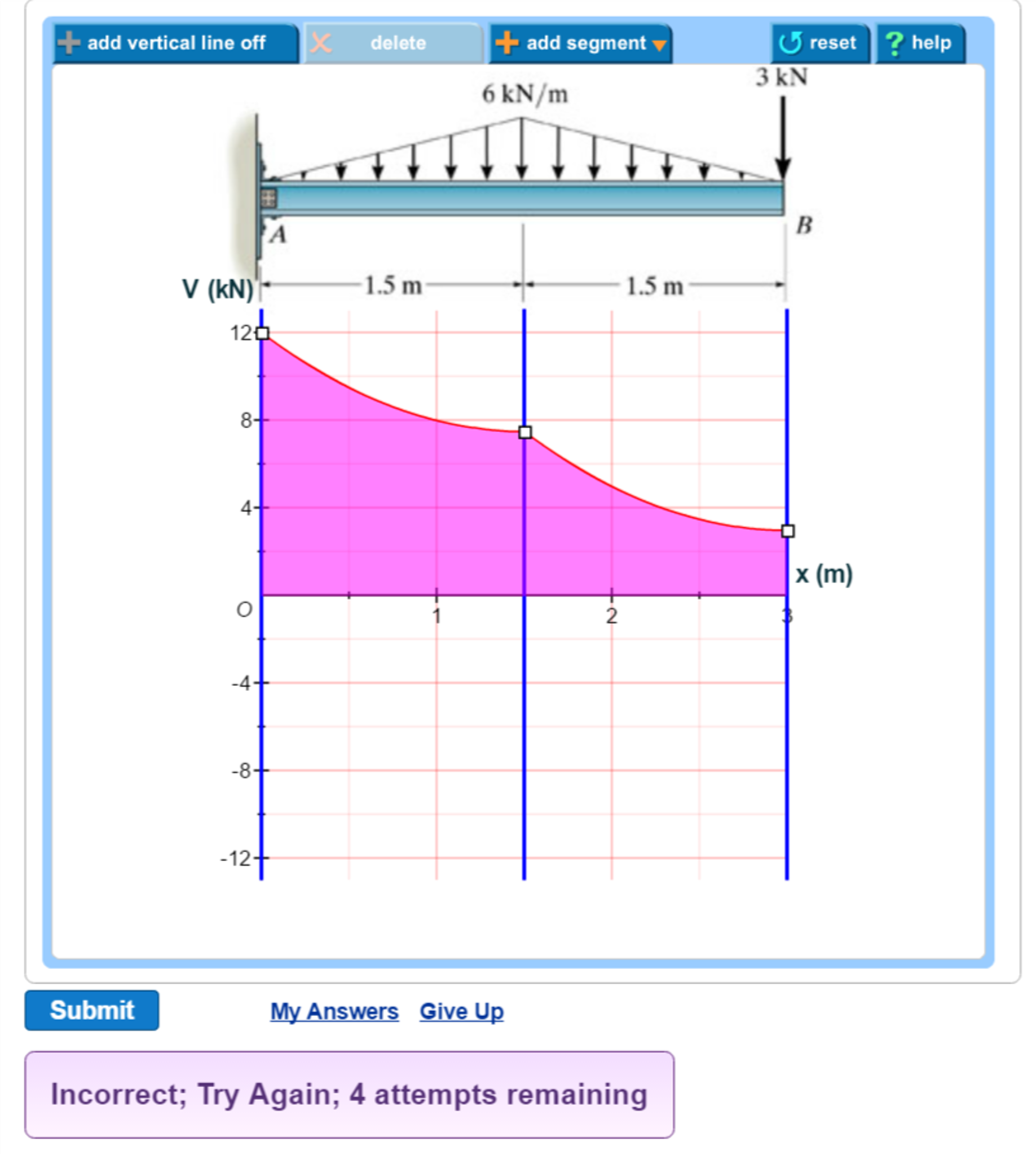
Note 1 - You should not draw an "extra" discontinuity line at the point where the curve passes the x-axis. Note 2 - Be sure to indicate the correct types of the ...
Select The Correct Shear Diagram For The Beam Figure 1 ...
Select the Shear Force Diagram for the following beam: This question was previously asked in. Gujarat Engineering Service 2019 Official Paper (Civil Part 2).
Shear Force Diagram - an overview | ScienceDirect Topics
Choose the correct shear diagram for the beam. Follow the sign convention. x=1.005 m. A uniform beam has a mass of 18 kg and rests on two surfaces at points A and B. Determine the maximum distance x to which the girl can slowly walk up the beam before it begins to slip. The girl has a mass of 50 kg and walks up the beam with a constant velocity.
Solved: Select The Correct Shear Diagram For The Beam. (Fi ...
Drawing Forces in the Beam: 12. Draw a diagram of the shear force in the beam. The shear in the end of the beam starts out at 0 lbs. However, since there is a reaction of 22,500 lbs on the left side of the beam, it will create that much shear in that location. The line load will cause this shear to decrease along the length
Solved: Part A Draw The Shear Diagram For The Beam. Begin ...
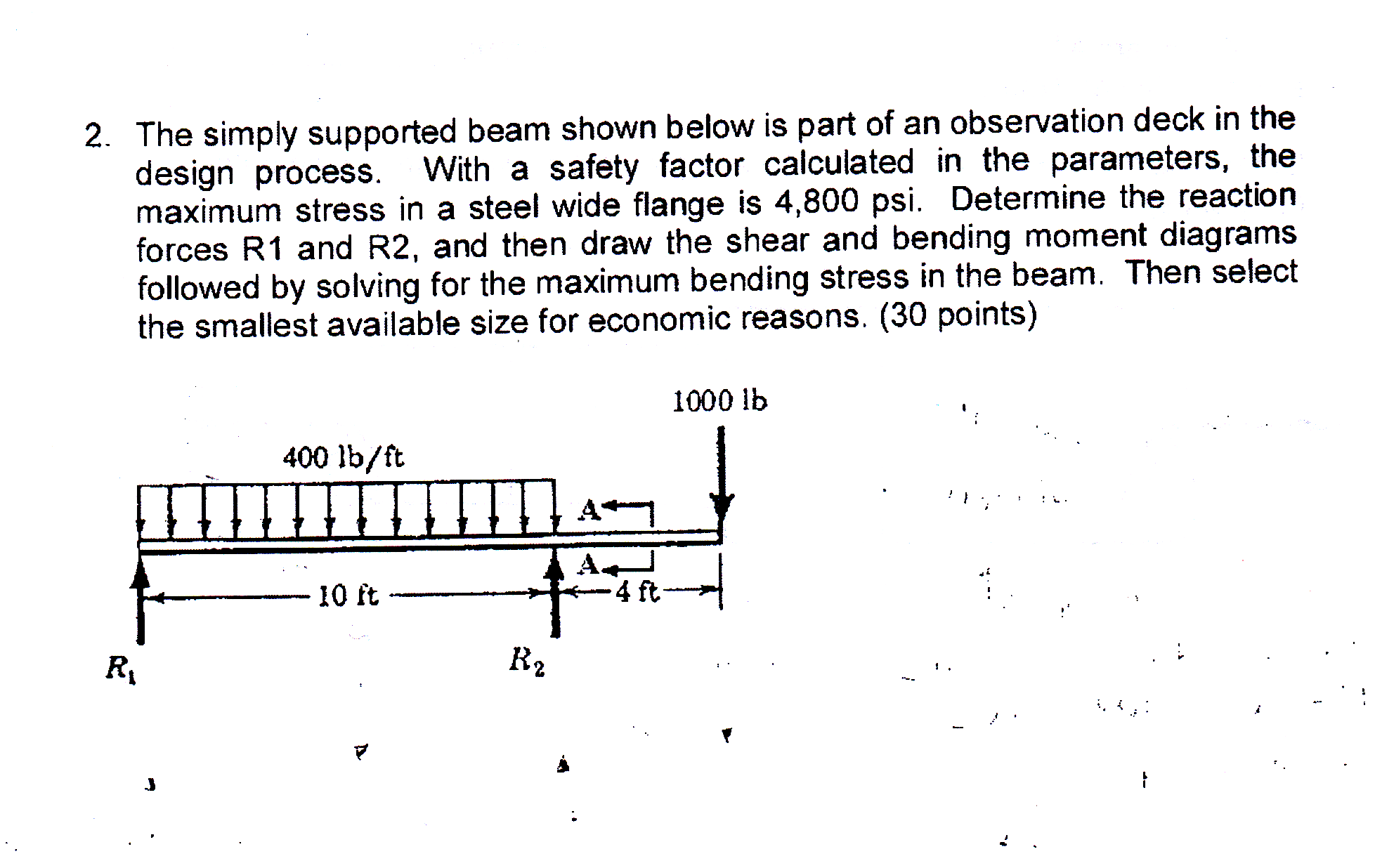
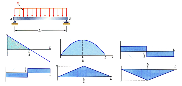
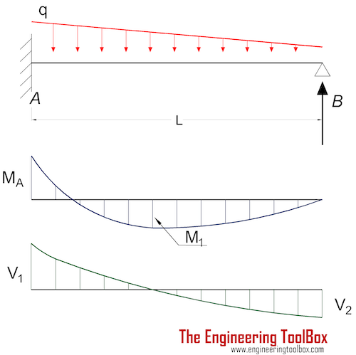
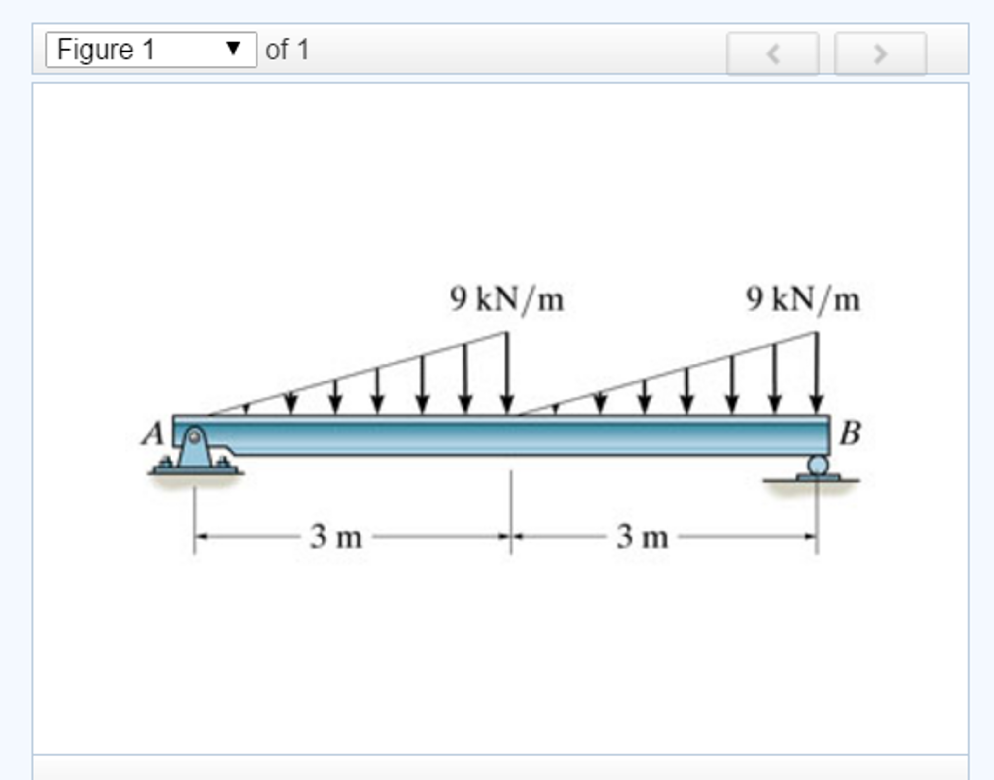
Shear and Moment Diagrams Consider a simple beam shown of length L that carries a uniform load of w (N/m) throughout its length and is held in equilibrium by reactions R1 and R2. Assume that the beam is cut at point C a distance of x from he left support and the portion of the beam to the right of C be removed. The portion removed must then be replaced by vertical shearing
stre
Select the correct shear diagram for the beam figure 1. A beam is shown in the figure below. Figure 1 select the correct shear diagram for the beam. Note make sure you place only one vertical line at places that require a vertical line. Draw the shear diagram for the beam. Follow the sign convention.

SAKURAI / Introduction to M-Theory and SuperStrings / The Final Visualization In Twenty Six Dimensions
Play this game to review Physics. Select the correct shear force diagram to match this bending moment diagram: Preview this quiz on Quizizz. Select the correct shear force diagram to match this bending moment diagram: ... The beam only has one support at 3m from the left hand side. <p>This is a bending moment diagram.</p> alternatives

34 Select The Correct Shear Diagram For The Beam. (figure ...
E is 2.5 × 10⁴ MPa and the moment of inertia I is 8 × 108 mm4, the correct comparison of the magnitudes of the shear force S and the bending moment M developed at the supports is Q8. A simply supported beam is subjected to a uniformly distributed load.
5.7 Normal and Shear Stresses | Bending of Beams | InformIT
Shear and Bending Moment Diagrams: The loading on most beams is such that the stress resultant on planes perpendicular to the axis of the beam consists of a shear force, V, and a bending moment, M. In determining beam responses, it is very convenient, if not essential, to first determine the shear and bending moment diagrams.
Solved: Select The Correct Shear Diagram For The Beam Sele ...
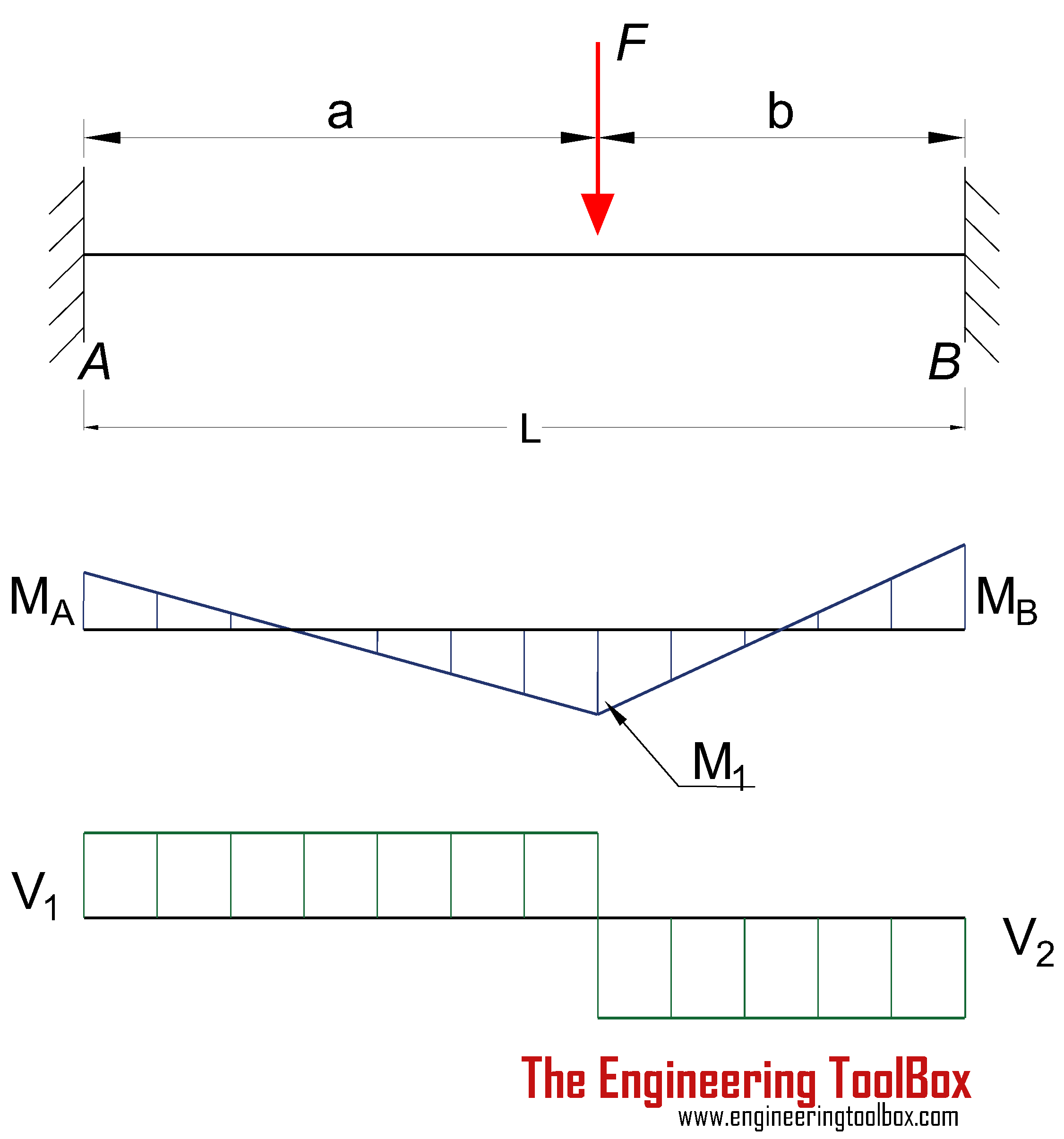
BEAM DIAGRAMS AND FORMULAS Table 3-23 (continued) Shears, Moments and Deflections 13. BEAM FIXED AT ONE END, SUPPORTED AT OTHER-CONCENTRATED LOAD AT CENTER

Learn How To Draw Shear Force And Bending Moment Diagrams ...
Part A Draw the shear diagram for the beam. Follow the sign convention. (Figure 1) Click on "add vertical line off" to add discontinuity lines. Then click on "add segment" button to add functions between the lines. Note - Make sure you place only one vertical line at places that require a vertical line.
Select The Correct Shear Diagram For The Beam Figure 1 ...
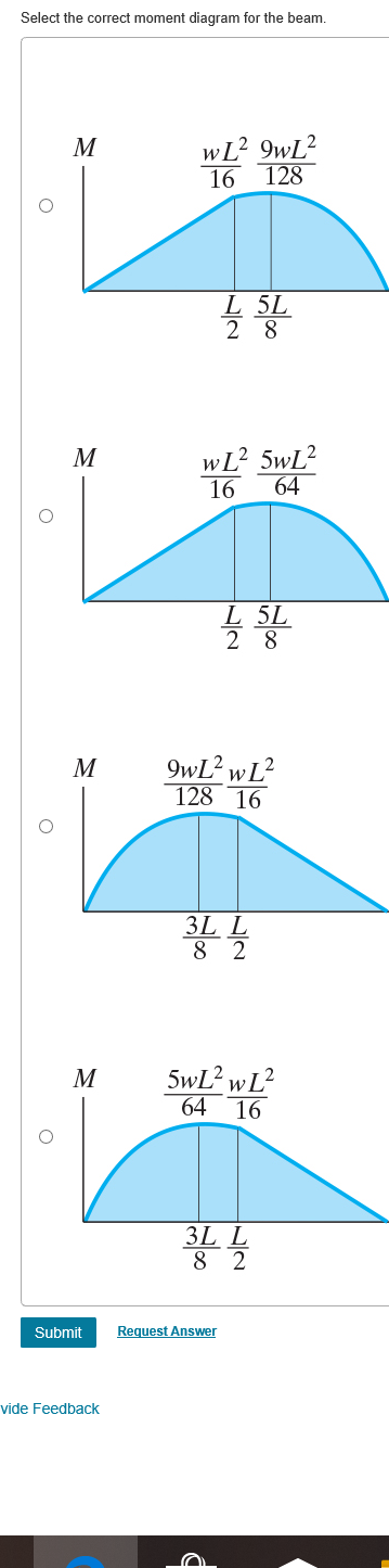
Choose the correct shear diagram from the column on the left. 2. Choose the correct moment diagram from the column on the right. Note: The moment diagrams on ...
Solved: Select The Correct Shear And Bending Moment Diagra ...
Select the correct shear diagram for the beam figure 1. This is the end of the preview. Draw the moment diagram for 10 points bonus for the beam shown in the figure below draw the shear diagram. Show all your work bonus points. In the figure below block 1 of mass m 1 slides from rest along a frictionl. The intensity of which varies from zero at ...
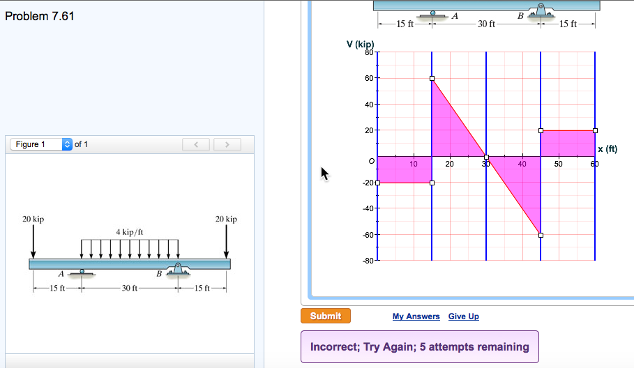
Statics 7.61 - Draw the shear and moment diagrams for the beam. - YouTube
Select the correct shear diagram for the beam. (Figure 1) Shear force. Shear force is the force in the beam acting perpendicular to its longitudinal axis. For design purposes, the beam's ability ...
AISC Beam Diagrams | Arch Exam Academy
For The Beam And Loading Shown A Select Correct Shear Bending Moment Diagram s B Determine Equations Of Curves Study. Problem 9 1 Two Beam Segments Ac And Cd Are Connected Toge the r At C By A Frictionless Pin Segment Is Cantilevered From R. 329 6 1 Draw The Shear And Moment Diagram s For Shaft Bearings At A B Exert Only Vertical Reactions On.
Solved: Select The Correct Shear Diagram For The Beam Sele ...
Calculating Shear Force Diagram - Step 2: Keep moving across the beam, stopping at every load that acts on the beam. When you get to a load, add to the Shear Force Diagram by the amount of the force. In this case we have come to a negative 20kN force, so we will minus 20kN from the existing 10kN. i.e. 10kN - 20kN = -10kN.
Solved: Given The Following Choices, Select The Correct Sh ...
Solved Draw The Shear Force And Bending Moment Diagrams For Cantilever Beam Determine A Position Of Point Contraflexure Bend Course Hero. Express The Internal Shear And Moment In Cantilevered Beam As A Function Of X Then Draw Diagrams Holooly. Solved Draw The Shear And Moment Diagrams For Loaded Cantilever Beam 1 Transtutors.
Shear force and bending moment diagram practice problem #3 - YouTube
(Figure 1) w L 3L 8 L wL 4 w L 5L L х 2 wL V w L 5L L х 2 ЗwL V wL 3L ЗwL 8 Select the correct moment diagram for the beam w L2 9WL2 128 16 L 5L 2 8 wL2 5WL2 М ...
Select The Correct Shear Diagram For The Beam Figure 1 ...
Free online beam calculator for generating the reactions, calculating the deflection of a steel or wood beam, drawing the shear and moment diagrams for the beam. This is the free version of our full SkyCiv Beam Software. This can be accessed under any of our Paid Accounts, which also includes a full structural analysis software.
Solved: Determine the correct shear diagram of the simply
beam from the left hand end and summing up the areas of shear force diagrams using proper sign convention. xThe process of obtaining the moment diagram from the shear force diagram by summation is exactly the same as that for drawing shear force diagram from load diagram.
Shear and moment diagram - Wikipedia
Choose the correct shear diagram for the beam. Follow the sign convention. Choose the correct moment diagram for the beam. Follow the sign convention. Show transcribed image text Expert Answer. Who are the experts? Experts are tested by Chegg as specialists in their subject area. We review their content and use your feedback to keep the quality ...
Solved: Part A Select The Correct Shear Diagram For The Be ...
Solved: Draw The Shear Diagram For The Beam. Follow The Si ...
Solved Problem 6.8 17 of 51> Review 2 kip/It 4 kip 20 kip-ft | Chegg.com
Solved) - For the beam and loading shown below, (a) evaluate shear force,... - (1 Answer) | Transtutors
Solved) - For the beam and loading shown below, (a) evaluate shear force.... - (1 Answer) | Transtutors
Select The Correct Shear Diagram For The Beam Figure 1 ...
Solved: Part A Draw The Shear Diagram For The Beam Click O ...
Solved Problem 07.039 - Shear and moment diagrams for a beam | Chegg.com
Solved: Select The Correct Shear Diagram For The Beam. (Fi ...
Select The Correct Shear Diagram For The Beam Figure 1 ...
Solved: Select The Correct Shear And Bending-moment Diagra ...
Solved: 1) Draw The Shear Diagram For The Beam. Follow The ...
For the beam and loading shown, (a) select the correct shear and bending-moment diagrams, (b) determine the equations of the shear and bending-moment curves. | Study.com
Solved: W Jс В Select The Correct Shear Diagram For The Be ...
Solved: W Jс В Select The Correct Shear Diagram For The Be ...
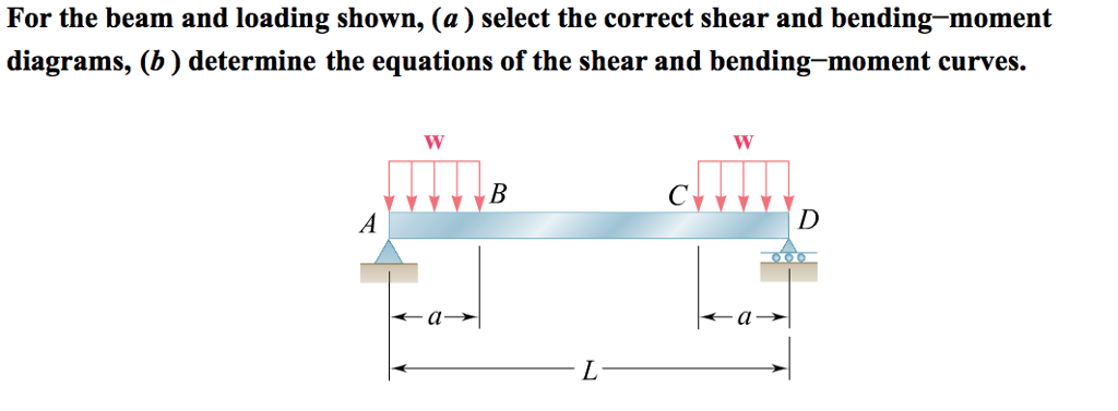
Solved: For The Beam And Loading Shown, (a ) Select The Co ...
Solved Problem 6.19 4 of 10 Part A Draw the shear diagram | Chegg.com
Solved: Draw The Shear Diagram For The Beam. Follow The Si ...
Solved: Part A Draw The Shear Diagram For The Beam. Follow ...
0 Response to "40 select the correct shear diagram for the beam"
Post a Comment