42 grasslin defrost timer wiring diagram
Determine model to be replaced (Grasslin or Competitors) ... Multi-Voltage Defrost Timers ... DTMV40 Time/Time –Electric Defrost Wiring Diagram. Description: Paragon Defrost Timer 8145 20 Wiring Diagram – Schematics And within Grasslin Defrost Timer Wiring Diagram, image size 450 X 1088 px, and to view image details please click the image.. Here is a picture gallery about grasslin defrost timer wiring diagram complete with the description of the image, please find the image you need.
Grasslin Dtav40 Wiring Diagram. For electric heat, hot gas or compressor shutdown defrost. The Grässlin DTAV40 Series Auto Voltage Defrost Timer is applicable to air defrost (compressor. Intermatic/Grässlin's Defrost controls just got even better! The DTAV40 defrost control automatically selects the appropriate voltage between Wiring Diagrams .

Grasslin defrost timer wiring diagram
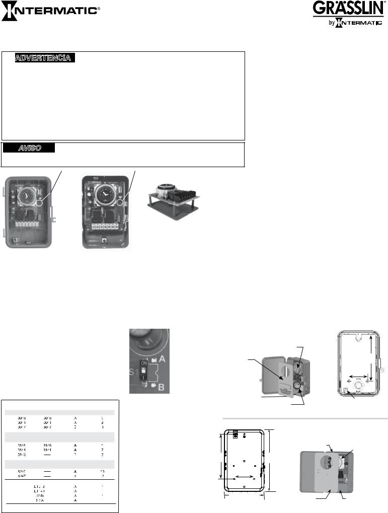
R efer to wiring diagrams 1 thru 12. ÒF Ó T erminal: The DTS X c ontains a normally c los ed c ontac t between terminals 1-F. This terminal may be us ed ... Grässlin Defrost Timers were designed specifically for OEM ... DTAV Series Common Wiring Diagrams & Enclosure/Mounting Dimensions 99.8 pages Diagram grasslin defrost timer wiring daufrus trasportopiu it dtmv40 series operating instructions manual pdf manualslib intermatic dtav40 installation time controls hvac r hv ac auto voltage manualzz multi 40 the first and only schematic 2020 heatcraft dtsz operation precision multiple official website your source for energy saving ...
Grasslin defrost timer wiring diagram. Grasslin 40a Defrost Timer Wiring Diagram – wiring diagram is a simplified usual pictorial representation of an electrical circuit. It shows the components of the circuit as simplified shapes, and the power and signal friends amongst the devices. A wiring diagram usually gives guidance approximately the relative direction and covenant of ... Grasslin Defrost Timer Wiring Diagram, Wholesale Various High Quality Grasslin Defrost Timer Wiring Diagram Products from Global Grasslin Defrost Timer.15 results for "grasslin defrost timer" Intermatic DTAV40 //v Time Initiated, Time Or Remote Temperature Or Pressure Terminated In Nema 3r Outdoor Plastic Enclosure. by Intermatic. $ $ 96 00 ... Determine model to be replaced (Grasslin or Competitors) ... Multi-Voltage Defrost Timers ... DTMV40 Time/Time –Electric Defrost Wiring Diagram.7 pages T 49f Wiring Diagram Swapping Timer On True T49f Freezer From Grasslin Dtsx Im 120tm To A Supco S814100 I Need Wirecolor. Diagram 8145 20 Defrost Timer Wiring With Temp Termination Full Version Hd Quality. Defrost Timer For True Part 831993 Restaurant Equipment Parts Food Service Partsfps.
Determine model to be replaced (Grasslin or Competitors) ... Multi-Voltage Defrost Timers ... DTMV40 Time/Time –Electric Defrost Wiring Diagram. Diagram Grasslin Timer Wiring Free Reske Paradiseoffires It. Grasslin Controls Dtsx B 240 Defrost Timer 010 0011a Rev A 0011b 74 75 Picclick. Dtmv40 Time Initiated Temperature Pressure Or Terminated Multi Voltage Defrost Timers. Defrost Timer Time Or Temperatu Re 120 230 1 Universal Grasslin Behler Young. Defrost Time Controls Hvac R Hv Ac. Grasslin Timer Wiring Diagram. Grässlin UK Connect wiring in accordance with wiring diagram. Do not combine timer to control a load on a separate supply circuit, which can be a different. Wired incorrectly need wiring diagram. grasslin timer need to no what wires go were there are 4 wires coming out the timer red and brown together white and. 24 Dec 2012 — Wiring diagram for grasslin defrost timer 08219056 - Hardware ... Link below has wiring diagrams and wiring manuals for 240V 8145-20
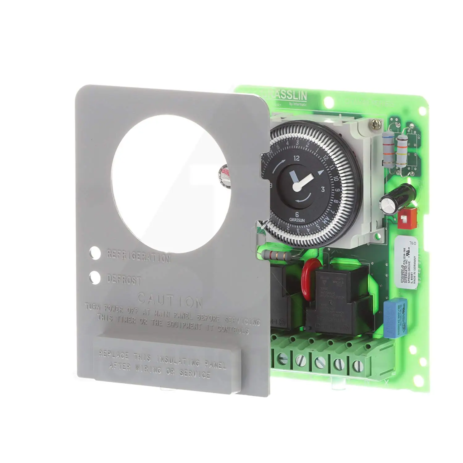
Grasslin Defrost Timer Wiring Diagram. July 25, 2018. Grasslin Defrost Timer Wiring Diagram powerful and user friendly time switches products for light and temperature control energy and hour metersTime Switch Technology HVACR Light Control Meters Imprint Grasslin Defrost Timer Wiring Diagram media inriver 6788 8171 ashx DTAV40 Fi ier PDFThe Gr ... the original wiring or the wiring diagrams indicated. MODE SELECTION (Light Blue DIP Switch): ... voltage as the defrost circuit (defrost heater, contactor. Grasslin Timer Wiring Diagram - Here we have another image Paragon Timer Wiring Diagram And Defrost Timer Wiring Diagram And featured under Grasslin Defrost Timer Wiring Diagram – Beamteam. We hope you enjoyed it and if you want to download the pictures in high quality, simply right click the image and choose "Save As".How to wire GM40 GM40AV ... Diagram grasslin defrost timer wiring daufrus trasportopiu it dtmv40 series operating instructions manual pdf manualslib intermatic dtav40 installation time controls hvac r hv ac auto voltage manualzz multi 40 the first and only schematic 2020 heatcraft dtsz operation precision multiple official website your source for energy saving ...
Diagram Based Magic Chef Fridge Wiring Diagram Ice Maker Wiring Harness Diagram
Grässlin Defrost Timers were designed specifically for OEM ... DTAV Series Common Wiring Diagrams & Enclosure/Mounting Dimensions 99.8 pages
Mx Intermatic Com
R efer to wiring diagrams 1 thru 12. ÒF Ó T erminal: The DTS X c ontains a normally c los ed c ontac t between terminals 1-F. This terminal may be us ed ...

Wiring For Grasslin Defrost Timer Model Number 010 0014 Fixya

Refrigerator Defrost Timer Wiring Diagram
Appliance411 Faq How Does A Frost Free Refrigerator S Defrost System Work
Intermatic Dtav40 Series Owner S Manual
2
Cheap Grasslin Timer Instructions Find Grasslin Timer Instructions Deals On Line At Alibaba Com

Grasslin Dtsx B 240 Hc Defrost Timer Ebay

Refrigerator Defrost Timer Wiring Diagram

Intermatic Fm 1 Series Operating Instructions Pdf Download Manualslib

13 3d Flooring Ideas In 2021 3d Flooring Washing Machine Washing Machine Repair

Solved Need Wiring Diagram Spst Power To Timer Timer To Fixya
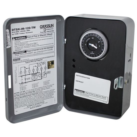
Defrost Timer For True Part 831993 Restaurant Equipment Parts Food Service Parts Partsfps
Grasslin Thermio Eco Bi1s Operating Manual Pdf Download Manualslib

Amazon Com Grasslin Dtav40 Universal Defrost Timer Patio Lawn Garden

Streamline Defrost Timer Installations With Intermatic S Dtav40 Series

Intermatic Defrost Timers And Manuals

Multi Voltage Defrost Timer 40 The First And Only Manualzz

Grasslin 120 208 Defrost Timer Electrical Timers Amazon Com
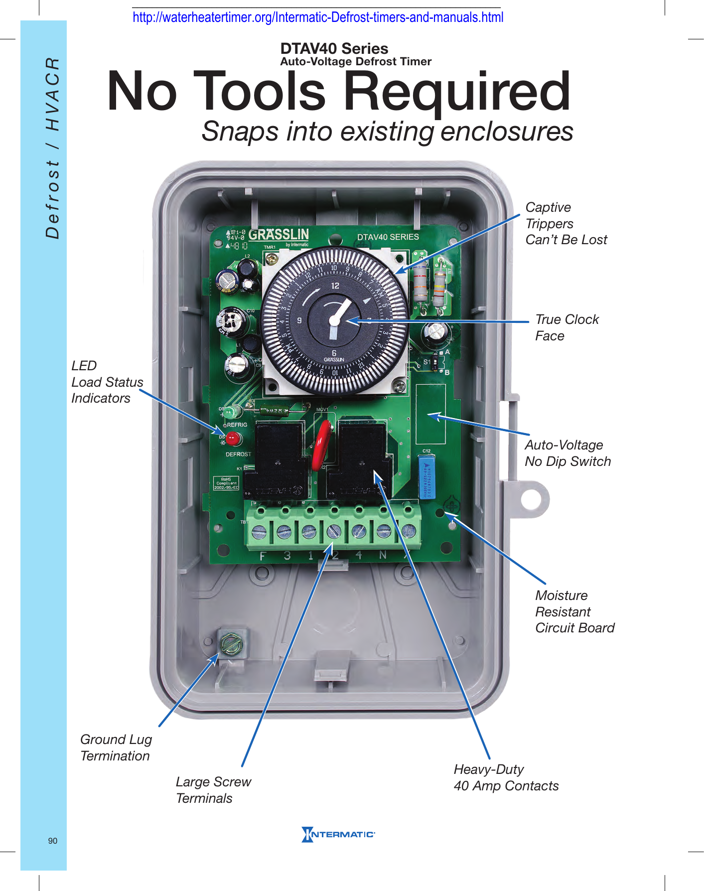
No Tools Required Snaps Into Existing Enclosures

Upgrade To The Grasslin By Intermatic Dtav40 And Make Installations A Snap Youtube
2

Delfield Refrigeration Mcc17925 Defrost Timer Hinged Parts
2
2

Commercial Defrost Controls Swh Supply Company

Short Term Electrical Load Forecasting Method Based On Stacked Auto Encoding And Gru Neural Network
2
2

Intermatic Product Catalog Pages 51 100 Flip Pdf Download Fliphtml5
1
8145 20
2

How Freezer Defrost Timer Operates Youtube
2

T 49f Wiring Diagram Swapping Timer On True T49f Freezer From Grasslin Dtsx Im 120tm To A Supco S814100 Timer I Need A Wirecolor To

Intermatic Dtav40m Intermatic Grasslin 120 240v 40a Nema3r Defrosttmr Wall Timer Switches Amazon Com
2
278fb2 Grasslin Timer Wiring Diagram Free Download Wiring Resources
2
2
0 Response to "42 grasslin defrost timer wiring diagram"
Post a Comment