41 fuel gauge wiring diagram
Faria Fuel Gauge Wiring Diagram - Gooddy, size: 800 x 600 px, source: gooddy.org How To Wire Up A Fuel Sending Unit Readingrat Net Exceptional, size: 800 x 600 px, source: carlplant.me If the image above is not really clear, please click the photo you intend to expand, then you will be required to an additional web page to display a more ...
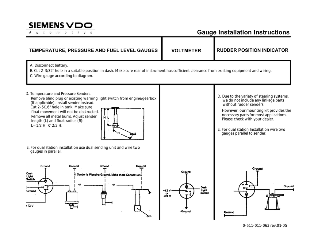
Wiring diagrams. 2 - 9. trim gauge, fuel gauge, fresh water gauge for level-type sensor. TU 1 . Only connect cables according to the electrical wiring diagram . VDO has tried to answer most of your questions regarding Installation and Trouble Note: These Instructions are for VDO Gauges and Accessories only.
Universal Fuel Gauge Wiring Diagram - universal fuel gauge wiring diagram, Every electric structure is made up of various distinct pieces. Each component ought to be placed and linked to other parts in particular manner. Otherwise, the structure will not work as it ought to be.
Fuel gauge wiring diagram
Fuel Gauge Sending Unit Wiring Diagram. Assortment of fuel gauge sending unit wiring diagram. A wiring diagram is a simplified traditional photographic representation of an electrical circuit. It shows the elements of the circuit as streamlined forms, as well as the power as well as signal links between the devices. A wiring diagram typically provides information…
1998 Chevy 1500 Truck 305 V8 Changed Fuel Pump Out And Found Relay Not Pulling In No 12 Volts On Coil Of. 1998 Chevy S 10 Fuel Pump Test Wire Flow Charts For. Need Fuel Pump Wiring Diagram Of 1999 Chevy Silverado. 2002 Yukon No Power To Fuel Pump The 1947 Present Chevrolet Gmc Truck Message Board Network. Gm S Series Pick Ups And Suv 1994 1999 ...
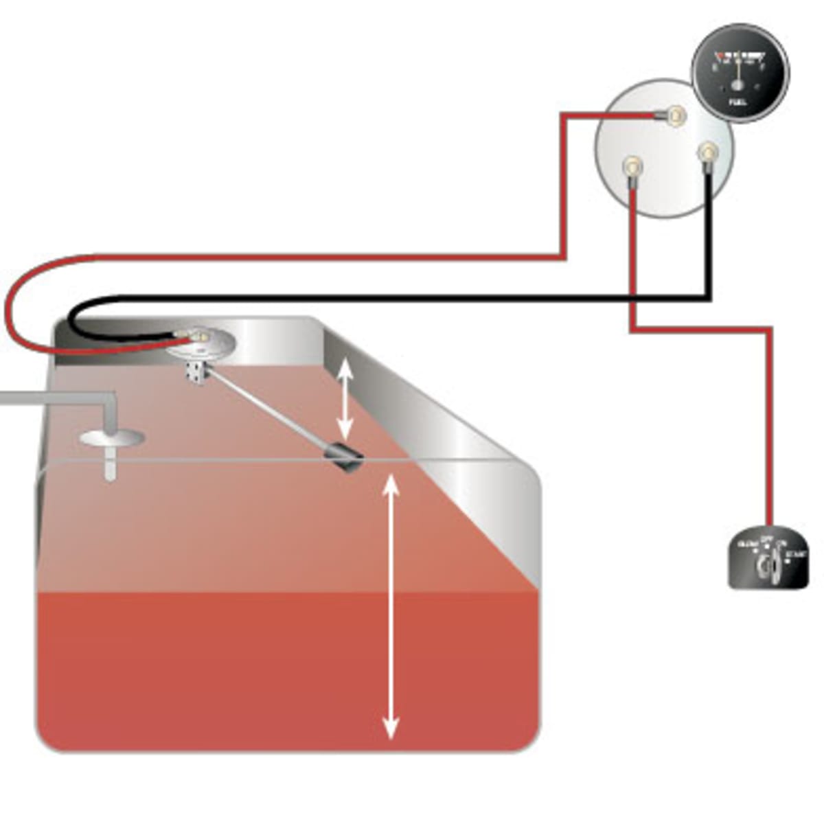
Fuel Gauge . Check the wiring diagram that comes with the kit and mark the back of the new fuel gauge with symbols for each post: "S" for the sender, "G" or "—" for the ground, and "I" for the ignition. Install the new gauge, reconnect the wiring and turn on the power. The fuel gauge should now show the correct fuel level in ...
Fuel gauge wiring diagram.
How To Test And Replace Your Fuel Gauge Sending Unit Sail Magazine. Yamaha fuel management wiring the gauges hull truth analog gauge conversion pro series and sending unit digital fm manualzz multi ribnet forums round gps sd faria including multifunction meter movement assy flow not getting data to for aw diagram a set 75 hp replacement trim sender engine instrument made easy smart options 05 ...
Fuel Gauge Sending Unit Wiring Diagram - wiring diagram is a simplified customary pictorial representation of an electrical circuit. It shows the components of the circuit as simplified shapes, and the skill and signal connections amid the devices. A wiring diagram usually gives opinion not quite the relative outlook and arrangement of ...
Basic Safe Electric Fuel Pump Wiring Diagram This is the basic wiring diagram for SAFE electric fuel pump wiring. The diagram is color coded per circuit and only a few things may need to be said. Fuel pump wiring for the RED circuit is generally going to carry a much higher current than the relay. So use a larger gauge wire for lower voltage drop.
Autometer Air Fuel Gauge Wiring Diagram Rate Fuel Gauge Wiring - Autometer Gauge Wiring Diagram. Additionally, Wiring Diagram provides you with enough time frame by which the assignments are to be accomplished. You will be able to learn exactly once the projects should be completed, that makes it easier for you to correctly manage your time ...
Smiths Fuel E Troubleshooting. Fuel gauge and sending unit wiring diagram the hull truth gas tank pour circuit layout of a level sensor to cell smiths e troubleshooting how wire up sw em for kus usa lexus 470 voltage divider on in dual units one replaced still not with pics honda voltages work 71 mustang 64 question problem xk jag working 1 electrical foxbody issues pcm confusing page 2 ...
From the thousands of photographs on the internet with regards to equus fuel gauge wiring diagram, we selects the very best choices having ideal quality simply for you all, and now this photos is considered one of pictures collections in this best pictures gallery in relation to Equus Fuel Gauge Wiring Diagram.I really hope you'll like it. This graphic (Gas Gauge Wiring Diagram Universal ...
"How Do You Wire A Fuel Gauge?Watch more videos for more knowledgeFuel Gauge & Sending Unit Troubleshooting - YouTube https://www.youtube.com/watch/z4c8_NnBW...
Nov 21, 2018 · Next I decided to check all the power wires to the ECM and also the grounds from a wiring diagram because the Mil is controlled by the ecm.Access Cummins Engine Controllers without a Wiring Harness. This page presents a method to extract data from an ECM without the use of bench calibration harness.
3. After wiring gauge/sender, calibrate them (Diagram E). With the tank empty, use the calibration screw to move the pointer to "E." When the pointer rests on "E" with the tank empty, the gauge and sender are calibrated and ready for use, and the gauge can be Wiring the Fuel Gauge: mounted. 1. Run wires from the adjustable fuel gauge ...
Feb 22, 2009 · Well, here are a few more wiring diagrams for Jeep Wrangler – this time for the Jeep YJ series years 1987 to 1994. The PDF includes ‘body’ electrical diagrams and Jeep YJ electrical diagrams for specific areas like: air conditioning units, typical jeep charging unit wiring diagrams, typical emission maintenance reminder wiring diagrams, front end lighting wiring diagrams and switches ...
Boat Fuel Tank Gauge Wiring Diagram - wiring diagram is a simplified standard pictorial representation of an electrical circuit. It shows the components of the circuit as simplified shapes, and the power and signal links surrounded by the devices. A wiring diagram usually gives information very nearly the relative incline and deal of devices ...
Ford Mustang Wiring Diagram for 1987-1993 Instrument Cluster By Jeff Warren / email: getina50@earthlink.net 1990-1993 Wiring Chart ... Fuel Gauge Feed Illumination Feed Right Turn Indicator Fasten Belts Indicator Battery Indicator Feed 1 Match to same colors as the 1987-1989 harness.
Fuel gauge wiring diagram: fuel gauge stopped working, fuel ...
2000 3500HD 6.5. Anyone have the diagram for a 2000, 6.5, 3500HD (straight axle) with dual tanks. I am in the middle of my build and am eliminating the fuel balance module and everything else beyond the front lift pump and sender. The stock wire harness goes to the balance module and then forward and backwards to both the lift pumps.
Smiths fuel gage troubleshooting
Description: Fuel within Stewart Warner Gauges Wiring Diagrams, image size 429 X 298 px, and to view image details please click the image.. Truly, we have been noticed that stewart warner gauges wiring diagrams is being one of the most popular subject right now. So that we attempted to find some good stewart warner gauges wiring diagrams picture to suit your needs.

Fuel gauge wiring - the hull truth - boating and fishing forum in ...
Wiring Diagram Fuel Gauge Manual - Today Wiring Diagram - Fuel Gauge Wiring Diagram Wiring Diagram consists of many in depth illustrations that show the connection of varied things. It includes guidelines and diagrams for various types of wiring strategies as well as other things like lights, home windows, and so on.

Sw-em fuel gauge
Mar 27, 2016 · Yes I have a 2001 Nitro NX 750 sometimes a fuel gauge works and sometimes it doesn’t have been riding on the lake with a lot of waves and whether the pounding may be taking a toll on it sometimes it works sometimes it don’t I check the wiring everything looks good and solid under the day can you please steer me in the correct way to diagnose this problem

Voltage divider on a fuel gauge in a car | all about circuits
Vw Beetle Fuel Gauge Wiring Diagram from littlevwbug.files.wordpress.com To properly read a electrical wiring diagram, one offers to know how typically the components in the system operate. For example , when a module will be powered up and it sends out a signal of half the voltage and the technician would not know this, he would think he ...

Lexus 470 fuel level sensor wiring diagram - lexusrumor.com
Variety of marine fuel gauge wiring diagram. A wiring diagram is a simplified standard pictorial depiction of an electrical circuit. It shows the parts of the circuit as simplified shapes, and the power as well as signal links between the devices.

Fuel level gauge | wema uk
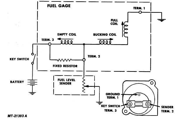
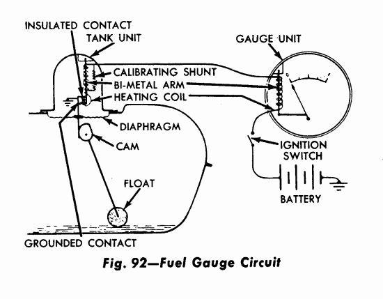
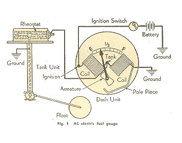
wire system that just has a tan wire from the gauge to the sending unit and a ground at each end of the circuit, and diagnosing problems with this system is quite simple. As background, here's how the "GM Standard" fuel gauge system works (see diagram). Dash Gauge: The dash fuel gauge has two coils in it - the limiting coil on the
Fuel gauge wiring (again!) - ribnet forums
VW Tech Article 1968-69 Wiring Diagram. Or, download image. ... Fuel Gauge Light K7 Resistance for Fuel Gauge K8 Brake warning light with test button O1
Smiths fuel gage troubleshooting
gauge dimmer control rw b rw b rw b rw b rw b rw b g fuel gauge & sender b i gauge voltage stabilizer lg/g gb brake switch g gp gp gp gp reverse lights & switch gn g gn gn gn g g fuel pump w w g lg/n (lg/n) * ts switch l turn signal flasher b cigar lighter fuel level speedometer tachometer oil pressure/water temperature diagram 3 - 67/68 mgb ...
Fuel gauge to fuel cell sending unit - honda-tech - honda forum ...
Step 4. Connect the "S" wire to the fuel-sender signal wire you removed from the stock fuel gauge. This wire is fed directly to the post on the fuel-level sender in the fuel tank. Twist these two wires together and cover them with a layer of electrical tape. Use your test lamp to determine the fuse for the dashboard instrument lights.
Vdo fuel tank gauge operating instructions | manualzz
Smiths Fuel Gauge Wiring Diagram. Effectively read a electrical wiring diagram, one offers to find out how the components within the program operate. For example , if a module will be powered up and it also sends out a signal of half the voltage in addition to the technician would not know this, he would think he offers a challenge, as he would ...

Fuel gauge on j.d. 2130 - tractorbynet
Here is a picture gallery about equus fuel gauge wiring diagram complete with the description of the image, please find the image you need. Find Equus Gauges & Accessories and get Free Shipping on Orders Over $99 at Summit Racing! Gauge Wiring Harnesses (2) Gauge Mounting Cups (2) Gauge Mounting Pods, Pillar (1) Equus - Equus Fuel Tank Level ...
Cannot get fuel gauge to work on 71 mustang gauge. | vintage ...
Wire a fuel gauge by first disconnecting the old dysfunctional unit to replace it with a new one. Obtain 12-volt power from the fuse box using a standard wire, and connect it to the positive terminal of the fuel gauge. Next, connect a wire from the float on the fuel tank to the negative terminal of the fuel gauge.
Technical - sw fuel gauge wiring woes!!! | the h.a.m.b.
wiring instructions. Always disconnect battery ground before making any electrical connections. Parts of the Fuel Level Sender Unit to be Ad Fuel Level Sender Installation: Refer to the VDO catalog for matching fuel gauges. The unit can be adjusted to read accurately in tanks from 6" to 23" deep. Diagram B I. Measure the depth of your fuel tank.
How to test and replace your fuel gauge and sending unit - sail ...
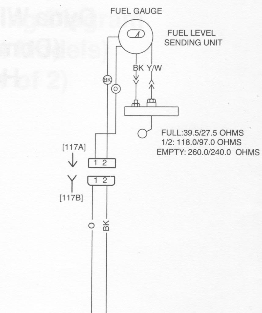
Moeller Gauge-Wiring Diagram 4″″ Universal Electric Fuel Sender Instructions Electric Fuel . Gauge pointer should be at the position shown in the lower portion of the diagram. To test senders, the resistance values are shown at minimum and full gauge scales. Fuel Systems (Marine) Voltage - "I" to "G" terminal - 10 to 16 volts.

Spridgetguru.com-tech index-fuel gauge wiring diagram
Trailer Wiring Diagram is a simple yet helpful way to know the proper way of wiring your trailer efficiently and properly. This will avoid unwanted connections, avoid unnecessary wiring, or increase safety by avoiding short circuits in the trailer when there are different types of wires to be hooked up.

Dual station converter
2. Using 18-ga. wire, connect the (G) terminal to a clean (rust/paint-free) Figure 4ground. 3. Using 18 gauge wire, connect the (I) terminal to a switched +12V source. 4. Using 18-gauge wire, connect the (S) sender terminal of the gauge to the fuel level sender. 5. Connect one the light wire to the dash lighting circuit or to a +12V switched ...

Wiring diagram 3 way switch lovely wiring diagram 3 way switch ...
Low fuel pressure can be caused by insufficient power or ground to the fuel pump or a malfunctioning fuel pressure regulator. No pressure can be due to a faulty relay, fuse, wire harness, or oil pressure switch, tripped inertia switch, or dried test fluid.

Circuit layout of a fuel-level sensor. | download scientific diagram
:max_bytes(150000):strip_icc()/4442635632_fcedeea5fc_o-5afb4c8f875db9003627413f.jpg)
4 reasons why your gas gauge isn't working
Electrical - foxbody fuel gauge issues | stangnet

Gas gauge diagram wiring schematic in 2021 | electrical diagram ...

Fuel gauge wiring problem - xk - jag-lovers forums

Spridgetguru.com-tech index-fuel gauge wiring diagram
Fuel sending unit wiring diagram for android - apk download

Circuit diagrams : electrical diagram fuel gauge
Troubleshooting and replacing your ford fuel gauge

Fuel gauge stuck on full - bmw 2002 and other '02 - bmw 2002 faq

Fuel gauge - working or not?

My fuel gauge doesn't work if it is grounded.

Fuel gauge wiring diagram | car gauges, wire, electrical wiring ...

1963-1967 corvette fuel gauge wiring schematic | willcox corvette ...

Fuel gauge and gas tank sending unit

Cara pemeriksaan sistem sinyal meter bahan bakar (fuel meter)
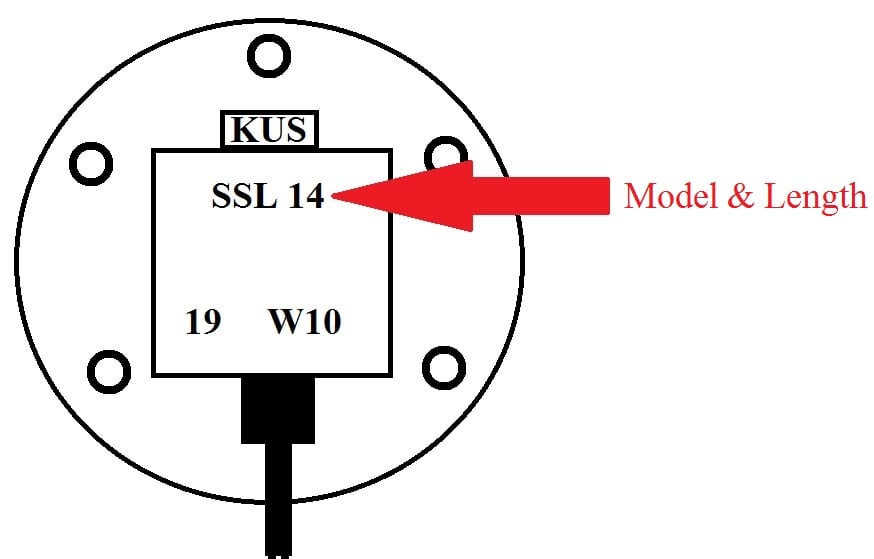
Gauge & sending unit | frequently asked questions | kus usa
Mga petrol gauge troubleshooting
1943 mb | willys mb | wwii jeep | mb gpw
Dual sending units to one fuel gauge? - the hull truth - boating ...

78 chevy fuel gauge not working - the 1947 - present chevrolet ...
Fuel gauge wiring confusing - page 2 - harley davidson forums
0 Response to "41 fuel gauge wiring diagram"
Post a Comment