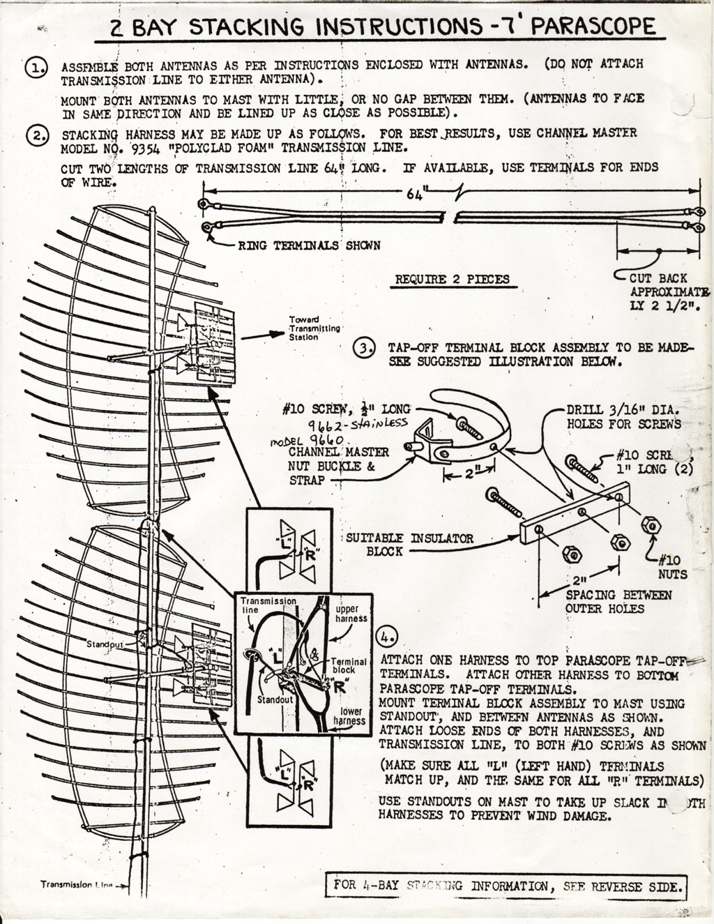
40 Channel Master Rotor Wiring Diagram
Replacement Parts - Channel Master Replacement Parts. Sold out Hardware Kit for Telescoping Mast Replacement hardware kit for the CM18xx telescoping mast $5.00. Hardware Kit for Digital Advantage 100 Hardware Kit for CM2020 $13.00. Butterfly Nut Kit for Advantage and Digital Advantage Series Antennas Butterfly Nut Kit for CM2016, CM2018, CM2020, CM3016, CM3018, CM3020, CM3671 ... Channel Master Rotor Wiring Diagram - autocardesign Channel Master Rotor Wiring Diagram- wiring diagram is a simplified all right pictorial representation of an electrical circuit. It shows the components of the circuit as simplified shapes, and the knack and signal associates amongst the devices.
Mercedes Benz Fault Codes – MB Medic This is a list of Mercedes-Benz specific Diagnostic Trouble Codes (DTC) or also known as engine fault codes. Please note that there are Check Engine / Service Engine / CEL fault codes which are stored in the Engine Control Unit (ECU).
Channel master rotor wiring diagram
PDF Instruction Sheet Hoja de Instrucciones ... - Channel Master time, unplug it from the wall outlet and disconnect the rotator cable. This will prevent possible shock, fire hazard and damage to the control due to lightning storms or power line surges. 21. Rooftop Installation Always use extreme caution when installing a rooftop antenna and rotator system to reduce the risk of falls. Wear rubber-soled Channel Master 9510a Wiring Diagram Channel Master 9510a Wiring Diagram. Wire hook up for Channel Master A We removed the wires to this unit and want to hook it back on. What color goes - Televison & Video. I suspect that the Radio Shack rotor was made by Channel Master. The ones that In an earlier post you said that the red wire to the rotor was the common wire and the black and ... Enigma machine - Wikipedia Enigma was designed to be secure even if the rotor wiring was known to an opponent, although in practice considerable effort protected the wiring configuration. If the wiring is secret, the total number of possible configurations has been calculated to be around 3 × 10 114 (approximately 380 bits); with known wiring and other operational ...
Channel master rotor wiring diagram. Radio Shack Rotator Box - QRZ Forums Also compatible with Channel Master, Magnavox, Audiovox, Antennacraft, RCA and other manufacturers 3 wire rotor control boxes. A better option is to replace the Radio Shack 15-1245 rotor control box with an RCA programmable rotor control box that includes a remote control: 96 Chevy C1500 5.7L Vortec Truck won't start ... - CarGurus 13/07/2014 · 96 Chevy C1500 5.7L Vortec Truck won't start, Replaced Fuel Pump, Filter & Has Spark. - Hey everyone, I have a 1996 Chevy C1500 with a 5.7L Vortec, I got ... OPEL KADETT OWNER'S MANUAL Pdf Download | ManualsLib Page 175 Body electrical system 12•7 11.2a Disconnecting the headlamp wiring 11.2b Rubber cover removed to expose the 11.3 Removing a headlamp bulb plug spring clip e) Always ensure that the new bulb is of the Sidelamp (front parking lamp) 12 Unclip and remove the bulb, separating its correct rating and that it is completely electrical connector at the first junction, not … Rotator System Instruction Manual (CM ... - Channel Master Channel Master Support. Support & Information. Other Product Support. Rotator System (CM-9521HD)
Channel Master parts, Rotor-Parts.com CDE rotator parts-> (192) Channel Master parts (1) Hardware & Accessories (12) Hy-Gain rotator parts-> (90) OLD Part Numbers (11) ORDERING INFO & STORE LOCATION (1) Manufacturers. Quick Find Use keywords to find the product you are looking for. Advanced Search. What's New? 50107-00 $17.50. Information. Shipping & Returns ... Rotor (rotator) question? - AVS Forum Are the voltages and controls universal from brand to brand? I have an unknown rotor on my mast that has five wires coming from it. A friend gave me a Channel Master Automatic Antenna Control Unit (Model 9510A) antenna rotator control. This unit only has three wire connectors, labeled 1 (Wide Wire), 2, and 3 and outputs 30V 1AMP. Antenna Rotator Overview and Instructions (CM-9521 & CM ... Remove the bottom (or access plate) of the drive unit housing and attach the rotor wires. All Channel Master antenna rotors use 3 conductor rotor wire. For runs up to 200ft, you can use 22ga, 3 conductor wire. Look in you instruction manual to see what wire size to use for longer runs. Most rotor wire will be color coded. Amazon.com: Customer reviews: Channel Master CM 9521A ... Built as well as the old Channel Master rotors. Easy to install and easy to use. I bought this one to replace my old Channel Master rotor that "locked up" in the middle of a Wisconsin winter. I had installed this one 20 years ago. I took this one apart after I installed my new Channel Master rotor.
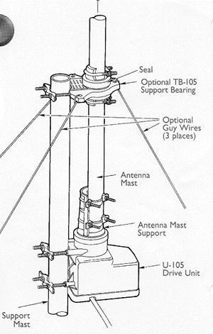
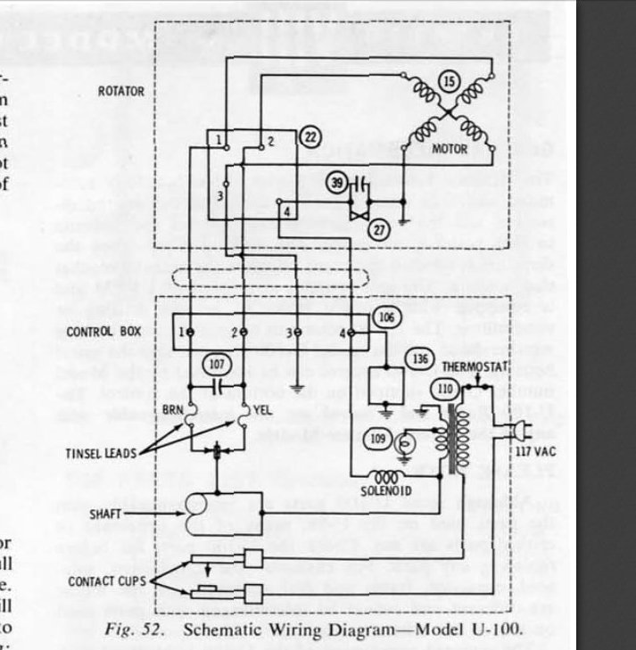
PDF Channel master antenna rotator model 9512 - Weebly Channel master antenna rotator model 9512 Channel master antenna rotator control unit cm9521hdxcu manual All channel master antenna rotors use 3 conductor rotor wire. this high quality rotator complete system will surely. you can connect a channel master model. antenna aerial rotator ar- 300 ar301 ar- 302 ar- 303, channel master, kerona, masterrotor, conrad - duration: 0: 58. PDF Antenna Rotator System Instruction Sheet - Channel Master Antenna, Masts, Coaxial Cable and Rotator Cable Figure 2 Figure 3 2. 5. 4. 1. Instruction Sheet 3. Contents: 1. Drive Unit Unidad de manejo Unité d'entraînement 2. Control Unit (Rotator wire not included) Unidad de control (El cable del rotor no está incluido) Unité de contrôle (Fil du rotor non inclus) 3. Remote Control Control remoto ... Channel Master 9510a Wiring Diagram - schematron.org The Channel Master is a rotor that turns an antenna to adjust the television signal for the best reception. Connecting the rotor is the process of wiring the base unit and the control unit to adjust the antenna from inside the house. You can connect a Channel Master model . Channel Master ® - Models CLASS 2 WIRING MAY BE USED. Vintage Alliance Model U-100 Tenna-Rotor Installation ... Unlike the newer systems that use a 3-wire control interface, the Alliance U−100 Tenna−Rotor uses a 4-wire cable. Control and feedback is about as simple as it gets with a motor turning the antenna mast and a solenoid in the control box that advances the dial as the antenna rotates. Cams on both ends open and close contacts as required.
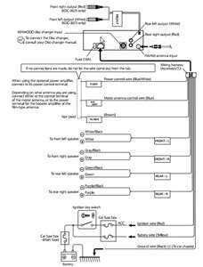
20 Most Recent Kenwood Sirius KDC-3025 CD Player Questions ...
Channel Master Rotor Wiring Diagram on PopScreen Shop for the latest products on Channel-Master-Rotor-Wiring-Diagram from thousands of stores at PopScreen. PopScreen - Video Search, Bookmarking and Discovery Engine PopCharts

Amazon.com: RCA VH226E Programmable Outdoor Antenna Rotator ...
Older Rotor with CM9537 Controller Unit - SatelliteGuys.US Then I press in 360 degrees and the rotor does not do a full turn to north (the other direction). I don't understand it. With the manual dialed control unit the antenna would go the full 360 degrees (north to north). But with the CM9537 the antenna stops at about 10 o'clock. ... BTW I have a Channel Master CM 3678 Ultra Hi-Crossfire TV Antenna ...

Vintage Alliance Model U-100 Tenna-Rotor Installation (Kirt's ...
eLearning - Amatrol Amatrol eLearning is the most comprehensive, complete technical training solution available today, consisting of hundreds of courses of technical training.

Hotwiring' antenna rotor? | AVS Forum
swanna-ochedzyn.pl Il y a 2 jours · The detail instruction, code, wiring diagram, video tutorial, line-by-line code explanation are provided to help you quickly get started with Arduino. If you do not have access to MATLAB, feel free to skip this section. In armature-controlled DC motors, the applied voltage Va controls the angular velocity w of the shaft. This library is compatible with all architectures so …
CHANNEL MASTER 9521A REMOTE CONTROL OWNER'S MANUAL | ManualsLib
Rotor Doctor Online Rotor Doctor Online. Welcome. Rotator Owners ! C.A.T.S. has been dedicated to serving all of your rotator needs longer than any current rotator service facility or rotator manufacturer in North America. The owner, Craig, has been playing with rotators since the mid-70's. We service, stock, and provide parts for top quality AMERICAN-MADE antenna ...
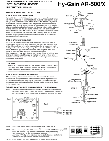
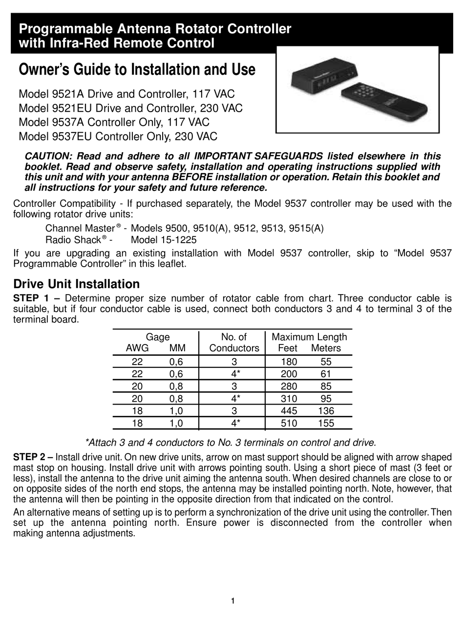
Hygain AR-500 ROTATOR, VHF/VHF BEAM, PROG REMOTE, 110/220 VAC ...
Online Essay Help - Get your assignment help services from ... Master's. Education. 10. View this sample Analysis (any type) Writer's choice. Undergrad. (yrs 3-4) Nursing. 2. View this sample Outline. How the courts address or respect our rights as citizens. Undergrad. (yrs 3-4) Political science. 2. View this sample ...

CDE rotator parts, Rotor-Parts.com
TV Antenna Rotators - Rotator System ... - Channel Master Buy antenna rotator system at the best price direct from Channel Master: The best complete antenna rotator system with Infra Red remote control.

Mikrowave1's Radio Project Resources - Home | Facebook
aqjj.sprawdzranking.pl Feb 13, 2022 · email protected]

Channel Master 9521A Remote control antenna rotor at Crutchfield
beautyfrau.de 1 day ago · Tanda cdi rosakfan x jalan. 4g15 Engine Wiring Diagram If you are searching for 4g15 Engine Wiring Diagram Download PDF or classics, do always check this 1 site. 18 Malaysia - Malaysia's Toyota Cars for sale in Malaysia - Malaysia's Largest Tanda throttle body rosak - datocracia. 2011 gear.
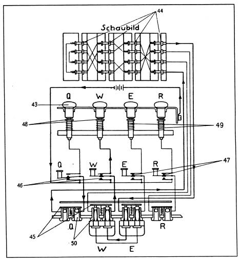
ENIGMA CIPHER MACHINE OPERATION AND WIRING DIAGRAMS
Strain measurement - Dewesoft Compact High-Channel-Count DAQ System ... Image 24: 4 wire or 6 wire bridge wiring . 4 - wire circuit. The 4-wire circuit is used for strain gage measurement with short lead wires. Its limitation is that the supply voltage is exact on the connector of the amplifier. 6 - wire circuit. The 6-wire circuit is recommended for the installation of long wires to the sensor. The sense wires are ...

CONTROLLER FOR ANTENNA Rotator Kenpro KR-400 - £68.36 ...
[Channel Master 9510] Automatic Antenna Rotator Controller 9520-9535 Channel Master Programmable Antenna Rotor Control Box (60% similar) Fits models works with any 3 conductor antenna rotor programmable 11 presets 9 volt battery backup lighted dial sync mode display memory gold led readout. The stand alone rotator control unit is perfect for those in need of a replacement an existing drive installation ...

Installing the RCA VH126N Antenna Rotator – VOXX International
channel master rotator | eBay Channel Master 3065 100' FT Antenna Rotor Cable 3-Conductor 22 AWG Wire Round. Brand New. 5.0 out of 5 stars. 5 product ratings. - Channel Master 3065 100' FT Antenna Rotor Cable 3-Conductor 22 AWG Wire Round. C $27.42. Top Rated Seller.
TV Antenna Installation Guide | The Solid Signal Blog
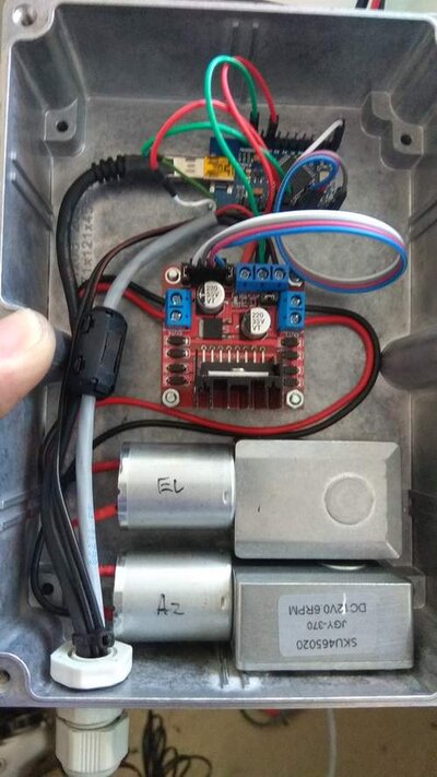
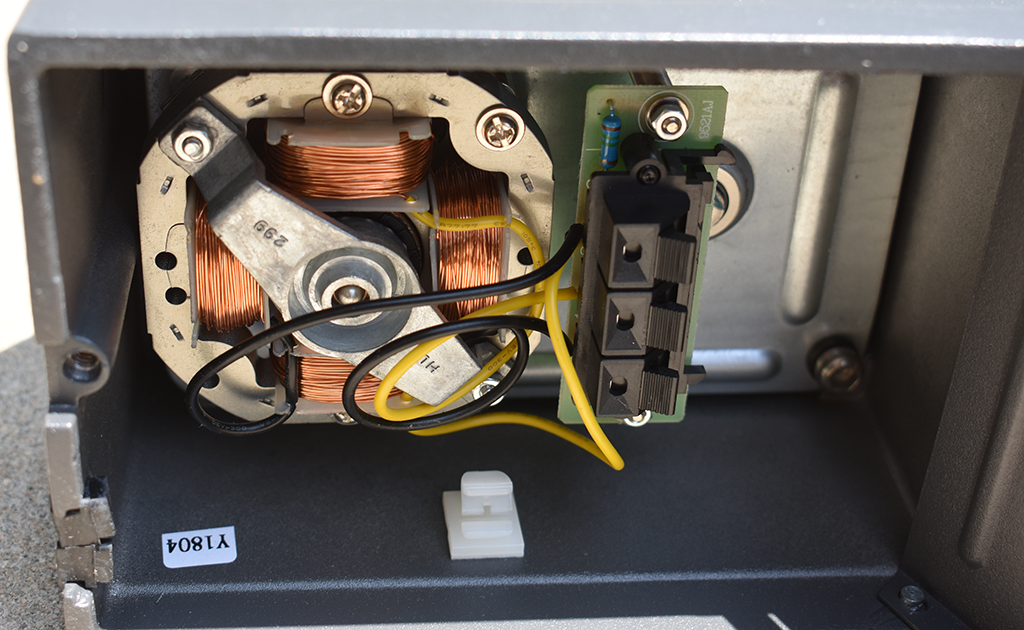
Wire Splice to Channel MAster Rotor Control The wiring diagram, and a picture of the inside of a typical mast mounted Channel Master rotor are here, you can see the colors of the wires in that photo are NOT the same colors as one of the wires you have, which is why you have to take it apart and look: ...
Question: motor voltage of old TV rotor from Alliance | QRZ ...
Product | Amatrol Amatrol offers excellent products for a wide range of technical education needs. At the core of our product offerings are learning systems. An Amatrol learning system contains everything you need to teach the subject: a trainer – either equipment-based or virtual – curriculum; teacher’s assessment guide; installation guide; and software as appropriate.
Antenna Rotator 9512 C Misc Channel Master Corp.; USA, build
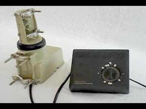
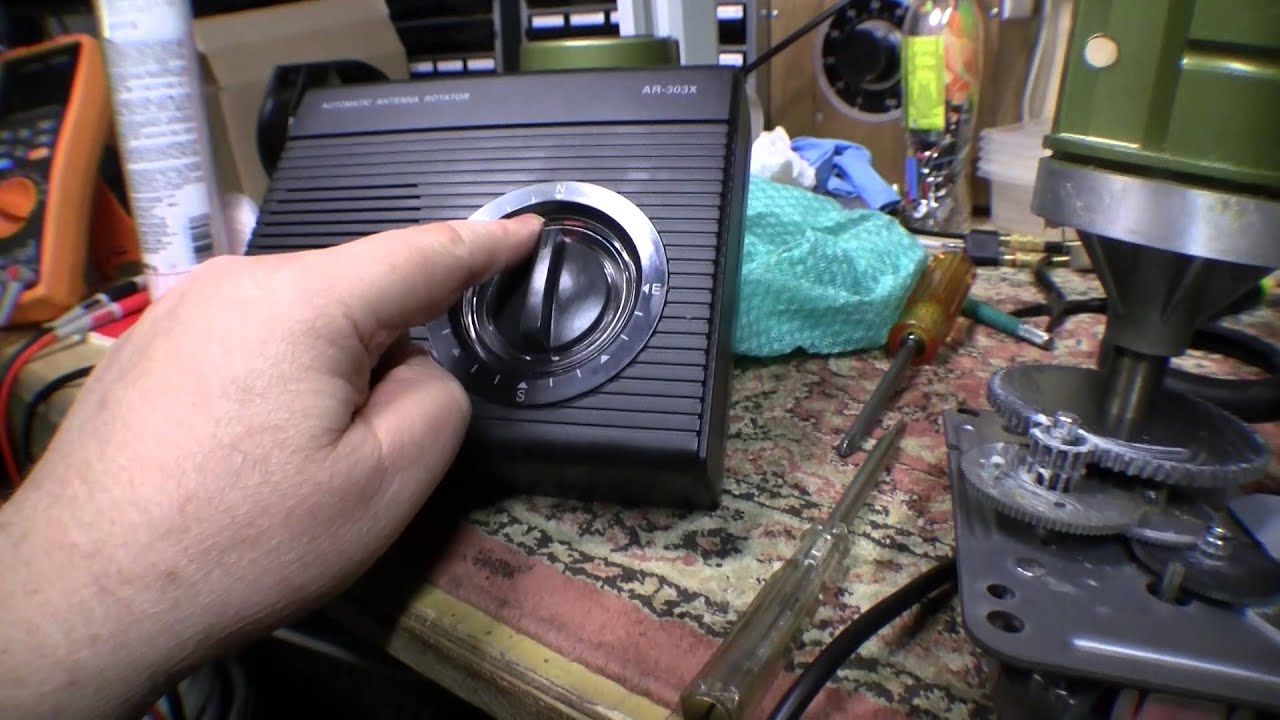
Rotor Control Unit Channel Master 9510A - YouTube Possibly broken control unit for antenna rotor.
Channel Master Model 3610 VHF TV-FM Antenna
PDF ROTOR SYSTEM OWNER'S MANUAL - RadioManual Wire the control to rotator as shown in figures 4 and 5, CAUTION - - SHORTS BETWEEN TE RMINALS OR GROUND ED LEADS MAY DAMAGE THE ROTOR. D, With the rotator sitting in the upright position and connected to the control unit, by the eight (8) W Ire cable, plug the control unit power cord into a 120 VAC 50 60 Hz wall receptacle.

CDE rotator parts, Rotor-Parts.com
Archerotor - Channel Master control box - YouTube Radio Shack rotor model Archerotor with the Channel Master 9510A control box
How I built a sun tracker for my solar panels
Archerotor 15-1225b Wiring Diagram - schematron.org Archerotor 15 B Wiring Diagram Antenna Rotor Likewise Channel Master Antenna Rotor Wiring Diagram photo, Archerotor 15 B Wiring Diagram. and observe safety, installation and operating instructions supplied with this unit and with safety, but improper installation or abuse of the unit, or the antenna .. over spray and cause electrical shock.
Mini Satellite-Antenna Rotator Mk1 - SARCNET
Channel Master 9510 Rotator Controller ... - Antique Radios Stavemaster1. Post subject: Re: Channel Master 9510 Rotator Controller with Damaged Gear. Posted: Aug Mon 24, 2020 12:42 pm. New Member. Joined: Aug Mon 24, 2020 1:51 am. Posts: 2. While attending a garage sale on Sunday August 23rd, I picked up a 9510A for 50 cents. A rare but not impossible accomplishment.
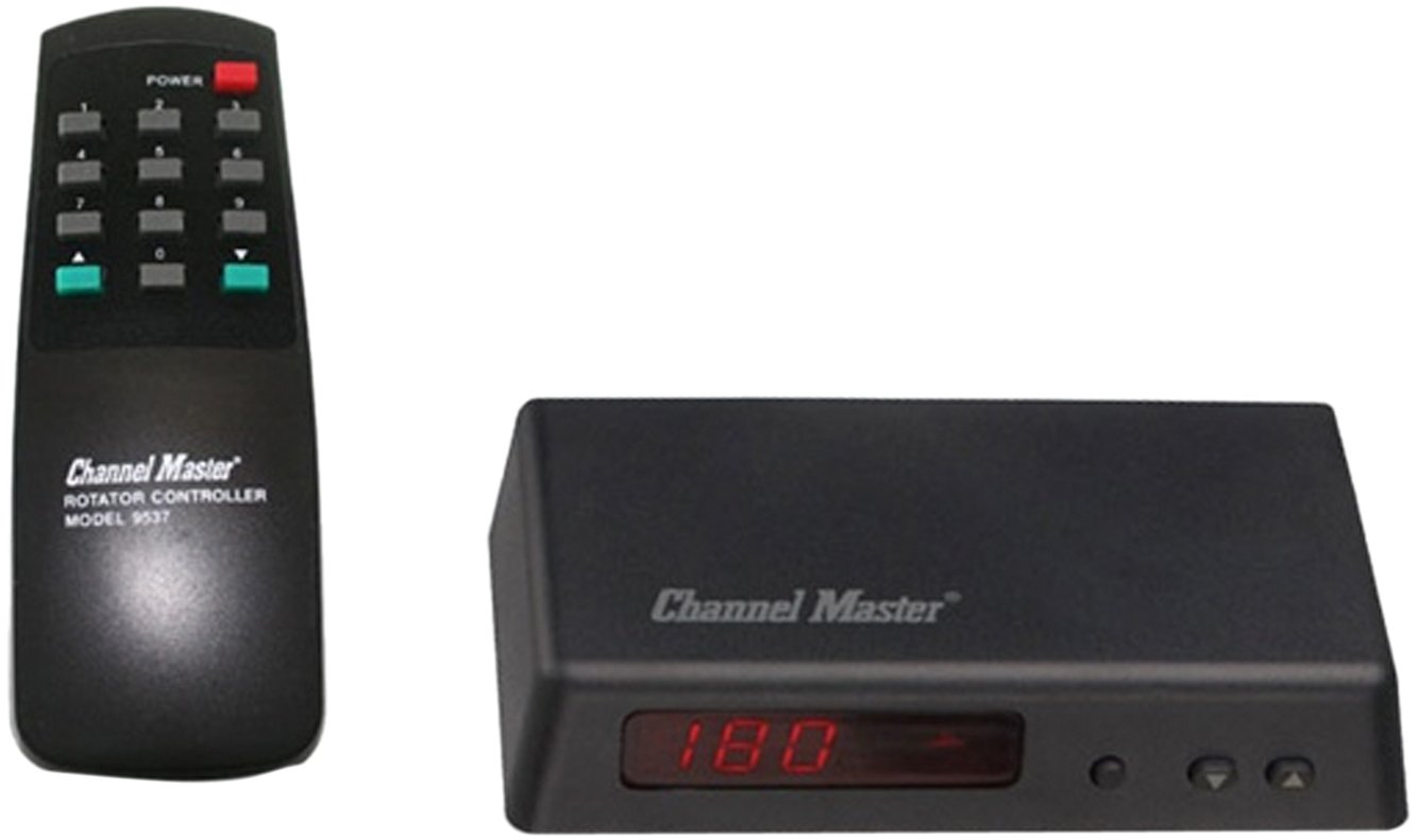
Channel Master CM 9537 Antenna Rotator Control Unit (CM9537 ...
PDF Outdoor Antenna Rotator RadioShack - RadioManual Channel Markers (84 x 1) Stud (4) User's Guide ... Slot 3-Wire Rotator Cable Third wire (copper) to Terminal 3 Center wire (copper) to Terminal 2 Silver-colored ground wire to Terminal 1 3-Wire Rotator Cable Strain Relief Slot Over for more instructions. Step 4: Mounting the Antenna 1. Insert the two U-bolts into the holes in the top portion of

Over the Air HD TV Antenna rotor from Channel master 9521A ...
5 Series MSO | Tektronix Channel 2 has a TLP058 Logic Probe connected to the eight inputs of a DAC. Notice the green and blue color coding, where ones are green and zeros are blue. Another TLP058 Logic Probe on Channel 3 is probing the SPI bus driving the DAC. The white edges indicate higher frequency information is available by either zooming in or moving to a faster sweep speed on the next …
Archerotor - Channel Master control box
poolcenter-koethen.de APRIL 24TH, 2018 - CHEVY 4X4 FRONT AXLE DIAGRAM FURTHERMORE P 0996B43F80C90F68 MOREOVER WHEEL BEARING QUESTION 3RD GEN 34561 ALSO FRONT AXLE 4WD I NEED WIRING DIAGRAM''chevy and gmc 4x4 front axles and parts drive shaft may 1st, 2018 - measuring diagrams how to measure axle diff all parts 4x4 front axle diff …

Tenna-Rotor U-100 Misc Alliance Manufacturing Co. Inc ...
How to Fix a Stuck Car Window - In The Garage with ... 02/05/2021 · Wiring. Power window wiring is specialized because the master switch is wired in series with all the other switches. When all the switches are at rest, both sides of the power window motor are grounded. But usually, the ground that feeds all the other switches (on the other doors) is fed to those switches through the master switch. In rare cases, the ground may be …
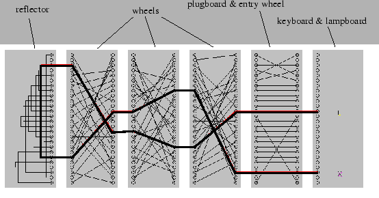
Operation of the Enigma machine with an example
centro ring – COMBATSHOP - But not both China Via Rj, Via Rj from China Supplier - Find Variety Via Rj from rj 45 ,rj 45 to usb ,test rj 45, Flanges Suppliers Located in China, Buy Via Rj Made in China on Alibaba You must set your GPS receiver to the proper datum in order to be able to use a topo map directly The potentiometer on top of the module can be used to adjust the range of the IR sensor Circuit Diagram and Explanation: The ...
Channel Master 4251 Tribute Page
Volkswagen - Beetle - Wiring Diagram - 2004 - 2008 Master Diagram Index See: Diagrams/Electrical Diagrams/Master Diagram Index How to Read Track Diagrams Page 4812 Wiring Diagram Layout 1 - Track Numbers Imaginary grid lines extending from the numbers on the bottom of the diagram toward the top of the diagram. These imaginary grid lines are used for identifying wire/circuit locations on diagrams. 2 - Reference of …
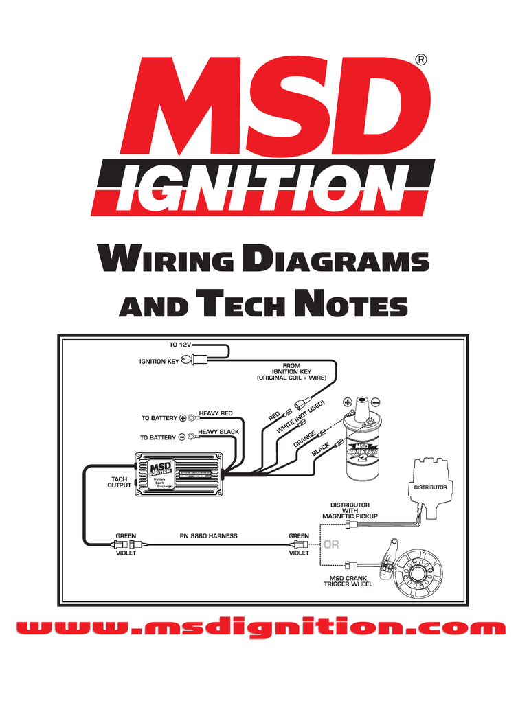
WIRING DIAGRAMS AND TECH NOTES | Manualzz
TORO WORKMAN MD SERVICE MANUAL Pdf Download | ManualsLib Brake rotor 20. Cotter pin 30. ... 2 used) 30. Tailgate channel 10. Latch washer (4 used) 21. ... GREEN BLUE Workman MD and MDX Main Electrical Harness Wiring Diagram ...

Good Vintage Channel Master Antenna Rotor Controller | #74214356
Alliance Tenna Rotor Wiring Diagram - easywiring The rotor case is almost the same for all the models. The alliance tenna rotor consists of two units. Nb 8671 Antenna Rotor Likewise Channel Master Antenna Rotor Wiring Diagram Wiring Diagram Of wires 4 or 5 and the limit switch or the potentiometer. Alliance tenna rotor wiring diagram. Source of data collector info sammler. …
Channel Master Rotor Wiring Diagram on PopScreen
Enigma machine - Wikipedia Enigma was designed to be secure even if the rotor wiring was known to an opponent, although in practice considerable effort protected the wiring configuration. If the wiring is secret, the total number of possible configurations has been calculated to be around 3 × 10 114 (approximately 380 bits); with known wiring and other operational ...
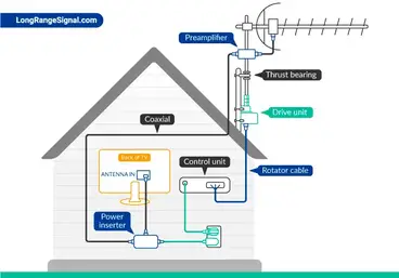
The Best Antenna Rotator for Your TV - Long Range Signal
Channel Master 9510a Wiring Diagram Channel Master 9510a Wiring Diagram. Wire hook up for Channel Master A We removed the wires to this unit and want to hook it back on. What color goes - Televison & Video. I suspect that the Radio Shack rotor was made by Channel Master. The ones that In an earlier post you said that the red wire to the rotor was the common wire and the black and ...

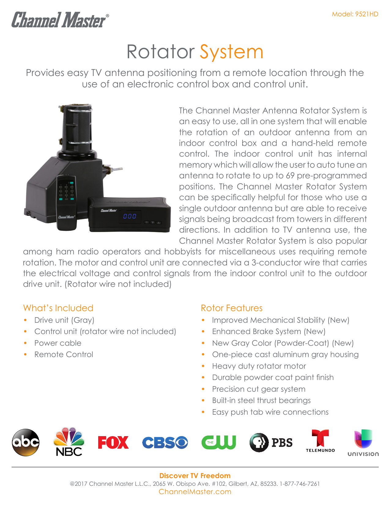
Rotator System
PDF Instruction Sheet Hoja de Instrucciones ... - Channel Master time, unplug it from the wall outlet and disconnect the rotator cable. This will prevent possible shock, fire hazard and damage to the control due to lightning storms or power line surges. 21. Rooftop Installation Always use extreme caution when installing a rooftop antenna and rotator system to reduce the risk of falls. Wear rubber-soled
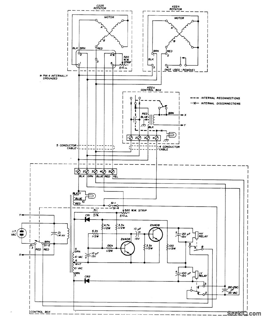
TWO_ROTATOR_CONTROL - Control_Circuit - Circuit Diagram ...
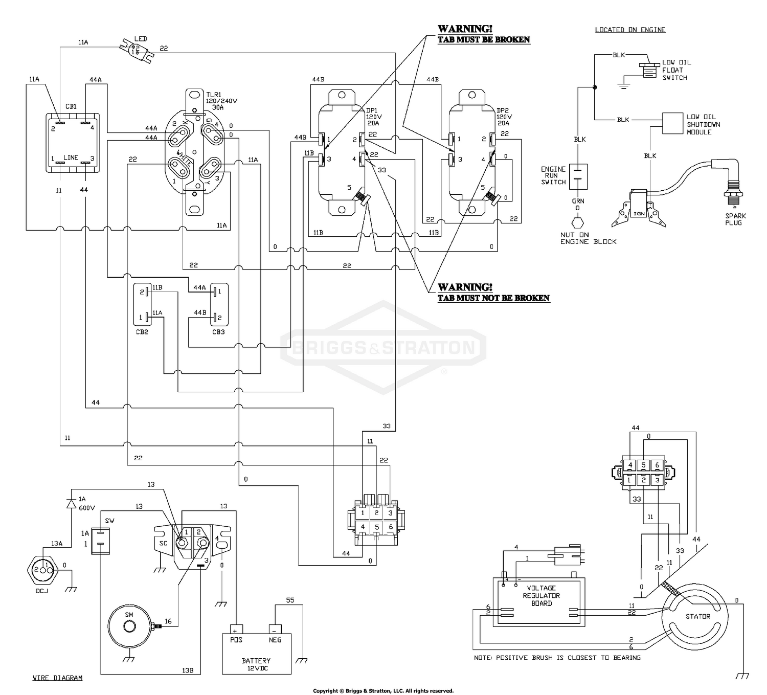
Briggs & Stratton Power Products_DEL_26072017021729 ...

How to Install a TV Antenna in Your Attic (and get rid of cable)
Fitting an Antenna Rotator - part 1
MINI-REVIEW: Channel Master CM9521HD Rotator | The Solid ...

How To Install A TV Antenna Rotor
MINI-REVIEW: Channel Master CM9521HD Rotator | The Solid ...

Channel Master Rotor Wiring Diagram on PopScreen
Channel Master CM-9521HDXDU Antenna Rotator Drive Unit ...

Channel Master Rotor - For Sale Classifieds
0 Response to "40 Channel Master Rotor Wiring Diagram"
Post a Comment