38 ge rr7 relay wiring diagram
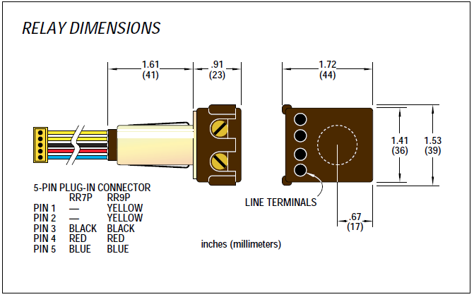
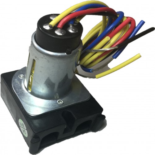
PDF Remote Control Low Voltage Switching RR9P Isolated pilot contact 5-wire relay with 5-pin connector The RR7P and RR9P relays are designed for simple connection to TLC panels. Other relay wire terminations are available, including: RR7 Standard 3-wire relay with stripped leads RR8 Pilot contact 4-wire relay with stripped leads RR9 Isolated pilot contact 5-wire relay with stripped leads GE Current - RR7 - Platt Electric Supply GE Current RR7 The GE Model RR-7 lighting relays is a mechanical latching-type unit designed for building automation systems. Each relay requires only momentary 24 volt AC switch circuit pulses to open or close line voltage circuits. All GE low voltage relays may be used to full-rated capacity for tungsten filament, ballast, or resistive loads.
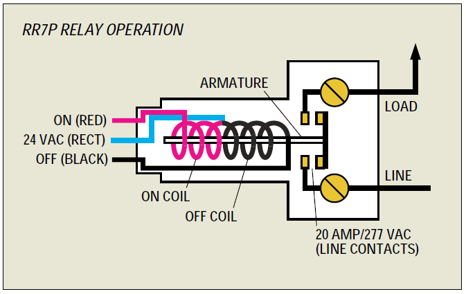
PDF 2R7 & 2R9 Relay Operational Summary 2R7 and 2R9 split coil relay's unique con-struction has only one movable part (the contacts). This reliable relay design has a proven failure rate of less than .001 per-cent. It offers both the popular GE RR7 relay footprint and functionality (3 wire control) along with extreme reliability. The following describes the actual inter-

Ge rr7 relay wiring diagram
35 Unique Ge Rr7 Relay Wiring Diagram | Relay, Diagram ... 35 Unique Ge Rr7 Relay Wiring Diagram- A manage relay is used in the automotive industry to restrict and tweak the flow of electricity to various electrical parts inside the automobile. They permit a small circuit to run a far along flow circuit using an electromagnet to govern the flow of electricity inside the circuit. rr7 ge relay wiring diagram - Wiring Diagram Rr7 Ge Relay Wiring Diagram. Free pdf search results latching relay i have a ge low voltage remote rr7 with blue black red wire am replacing the ceiling fan another light relays in lighting systems to control lights or motors system 24 emergency ul924 rated 277v contactor coil and an 8 group input module 48 capacity interior kele com controls ... Rr7 Relay Wiring Diagram - schematron.org Rr7 Relay Wiring Diagram. I have low voltage wiring using GE rr7 relays. there are two relays which will not work because a mouse ate the Look at the diagram: graphic. For indoor use only! For use with RR7/9 type relays! For use with other systems, contact technical support! Do not run any Greengate low voltage wiring in the.
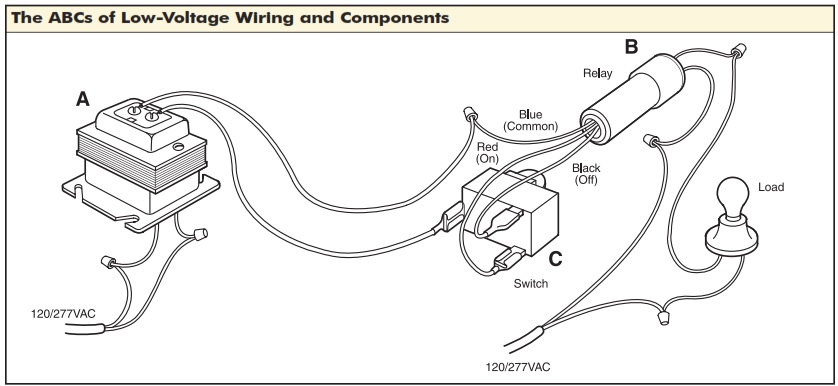
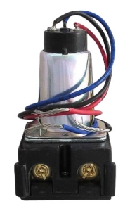
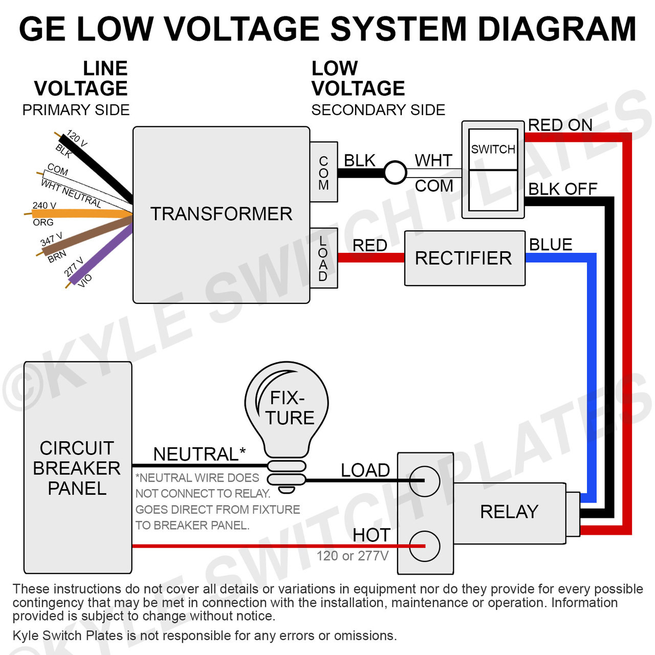
Ge rr7 relay wiring diagram. RR-7, RR-9 | GE Mechanical Latching 24 VAC Lighting Relays ... GE Model RR-7 and RR-9 lighting relays are mechanical latching-type units requiring only momentary 24 VAC switch circuit pulses to open or close line voltage circuits. All GE low voltage relays may be used to full-rated capacity for tungsten filament, ballast, or resistive loads. The Model RR-9 includes an auxiliary contact on the low voltage side for status indication. GE RR7 Low Voltage Remote Control Relay Switch RR7P3 The GE RR7PBP low voltage relay is a direct replacement for older GE brand RR2, RR3, RR5, and RR7 mechanical latching relays. Like the original models, the RR7PBP is a standard solenoid relay designed for use with GE RS series unlighted switches. Generally, the red was for on, the black for off, and the blue was the common. Best Wiring Diagram Symbols Automotive Led Tube Light ... Wiring diagram symbols automotive. I m an auto technician for over twenty years i ve always loved the electrical side of auto repair. Automotive wiring diagram basic symbols. Electrical connectors consist of plugs. The battery symbol appears to be made of layers or plates common to internal battery construction. ... Ge-Rr7-Relay-Wiring-Diagram - RAUR.US The ge rr7 relay is a 'latching relay'. Diagrams rr7 relay wiring diagram ge at, flasher relay wiring diagram carlplant with, 12v relay wiring diagram carlplant inside, 30a 5 wire relay wiring pin diagram driving lights inside 12 volt at, how to wire a relay 5pin and 4pin bosch style youtube relay best wiring diagram, phase controller wiring ...
Ge Timer Switch Wiring Diagram - easywiring Ge rr7 relay wiring diagram. Assortment of ge dryer timer wiring diagram. Dsxh47eg dryer pdf manual download. A 8 pin timer are used. Whirlpool Fefl88acc Electric Range Timer Stove Clocks And Appliance Timers. Download Manual for Model GTD42EASJ2WW GE DRYER. Ge Dryer Wiring Diagram Timer Electric Free Download Car Profile New Ge Dryer Start ... GE Low Voltage Relays, Remote Control Relay Switches ... The RR7 relay and is the proper replacement for the following discontinued GE relays: RR2, RR3, and RR5. The RR7 relay is also a compatible replacement for a standard Bryant solenoid relay and has a split low voltage (24V) coil to move the line voltage contact between latched ON and OFF positions. Ge Rr9 Relay Wiring Diagram - schematron.org Ge Rr9 Relay Wiring Diagram. The GE Model RR-7 and RR-9 lighting relays are mechanical latching-type units designed for building automation systems. All GE low voltage relays may be used to full-rated capacity for tungsten filament, ballast, or resistive loads. The Model RR-9 lighting relay includes an. 12v relay wiring diagram ge lighting ... Ge Smart Switch 3 Way Wire Diagram - Studying Diagrams 35 Unique Ge Rr7 Relay Wiring Diagram Relay Diagram Electromagnet . I have a 3-way switch that I believe is wired similar to the diagram I attached. Ge smart switch 3 way wire diagram. You cannot use dumb 3-way switches with most smart switches You must purchase the matching GE add-on switch to wire with your GE smart master switch. All ...
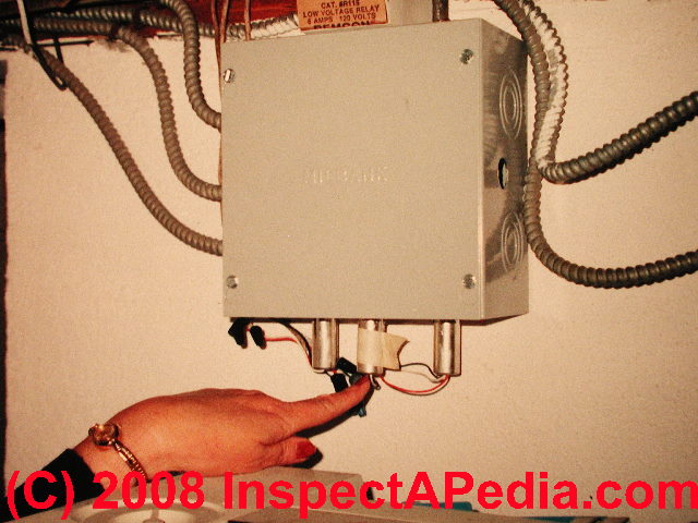
GE Low Voltage Light Switch & Relay Wiring Guide - Download Use this Kyle Switch Plates exclusive detailed instructions for installing newer GE RS2 series low voltage switches in remote control wiring systems using RR7, RR8 or RR9 mechanical relays and RT series transformers. One download per purchase. Download available for 72 hours. For private use only - no sharing or posting. PDF Basic 16 relay SINGLE SEQUENCER HOOK-UP DIAGRAM System as ... HOOK-UP DIAGRAM. WIRE SIZES All low voltage wiring within cabinet: 22 AWG minimum. Low voltage between cabinets: 22 AWG minimum except 18 AWG minimum on 24 VAC as shown. 18 AWG minimum (between cabinets) CAUTION DO NOT connect more than one RR relay coil to any sequenced (numbered) terminal. 146-0041-03c Next to BLUE wires of RR7 or RR8 relays Rr7 Relay Wiring Diagram Rr7 Relay Wiring Diagram RR7 Sensors: How Can I Troubleshoot GE RR7 Relays And Sensor Switch You should measure about VDC at the red and black wires of the sensor. This makes remote switching of lighting circuits . RR7. Standard 3-wire relay with stripped leads. RR8. Pilot contact 4-wire relay with stripped leads. RR9. GE RR7 low voltage relay. Ge Rr7 Relay Diagram - Wiring Diagram Pictures The GE RR7 low voltage relay is a direct. GE low voltage wiring switches, relays and junction box (C) InspectAPedia . See Three-wire to Touch-Plate® Wiring Diagram. 28VDC latching relay, whereas the the GE® relay (RR-7) is a dual coil, 24VAC latching relay, and the Remcon®.The relay should "click" and the Relay Indicator should change state.
low voltage relay light switch Off 75% - www.gmcanantnag.net
PDF Lighting Controls LIGHTING CONTROLS LIGHTING CONTROLS GE LIGHTING RELAYS MODELS RR-7, RR-9 382 2004 KELE CATALOG • • USA 888-397-5353 • International 901-382-6084 The relay employs a split low-voltage coil to move the line voltage contact armature to the on or off latched position.

70 Lovely Idec Relay Wiring Diagram | Relay, Electromagnet ...
Ge Low Voltage Switch & Relay Wiring Instruction Guide ... GEL-WIRING View Details exclusive instructions for installing newer GE RS2 series low voltage switches in remote control wiring systems using RR7 RR8 or RR9 mechanical relays and RT series transformers55. For private use only - no sharing or posting. Do not connect any single low. 12v relay wiring diagram ge lighting.
Wiring Vintage GE Low Voltage Lighting Master Control Panel ...
GE Low Voltage Switch & Relay Wiring Instruction Guide Description. Read this Kyle Switch Plates exclusive instructions for installing newer GE RS2 series low voltage switches in remote control wiring systems using RR7, RR8 or RR9 mechanical relays and RT series transformers. Included for free with the purchase of any GE low voltage lighting component. Kyle Switch Plates is the premiere choice for ...

GE Low-Voltage Rocker Switch Replacements - Forum - Bob Vila
Rr7 Relay Wiring Diagram - schematron.org Rr7 Relay Wiring Diagram. I have low voltage wiring using GE rr7 relays. there are two relays which will not work because a mouse ate the Look at the diagram: graphic. For indoor use only! For use with RR7/9 type relays! For use with other systems, contact technical support! Do not run any Greengate low voltage wiring in the.

Miller MILLER AIR PAK User manual | Manualzz
rr7 ge relay wiring diagram - Wiring Diagram Rr7 Ge Relay Wiring Diagram. Free pdf search results latching relay i have a ge low voltage remote rr7 with blue black red wire am replacing the ceiling fan another light relays in lighting systems to control lights or motors system 24 emergency ul924 rated 277v contactor coil and an 8 group input module 48 capacity interior kele com controls ...

User Guide
35 Unique Ge Rr7 Relay Wiring Diagram | Relay, Diagram ... 35 Unique Ge Rr7 Relay Wiring Diagram- A manage relay is used in the automotive industry to restrict and tweak the flow of electricity to various electrical parts inside the automobile. They permit a small circuit to run a far along flow circuit using an electromagnet to govern the flow of electricity inside the circuit.
Just a flip and a relay and on comes the light- Low voltage ...

Where can I find SCHEMATIC for a GE Low voltage relay model ...
Lighting Control Panel
Greengate NeoSwitch - PIR RR7 Compatible Wall Switch Sensor ...
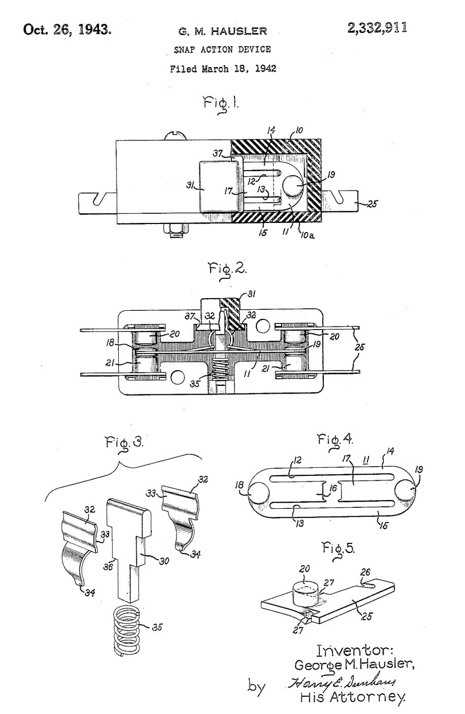
A remote control apparatus - Patent 0323919
GE Controls | Installation Guide | Centralized Lighting ...
GENERAL ELECTRIC RR7 Lighting Control Relays | WESCO
Low Voltage Relays in Lighting Systems Low Voltage relays ...
GE Lighting Control System with 6 RR9P Relays and an 8-Group ...
Problem with GE RR7 low voltage relay. | Terry Love Plumbing ...
GE Lighting Control System with 6 RR9P Relays and an 8-Group ...
Low Voltage Relays in Lighting Systems Low Voltage relays ...

GE RR7 LOW VOLTAGE RELAY General Purpose Relays Relays

Ford Mondeo '03 EWD Taiwan PDF | PDF | Manufactured Goods ...
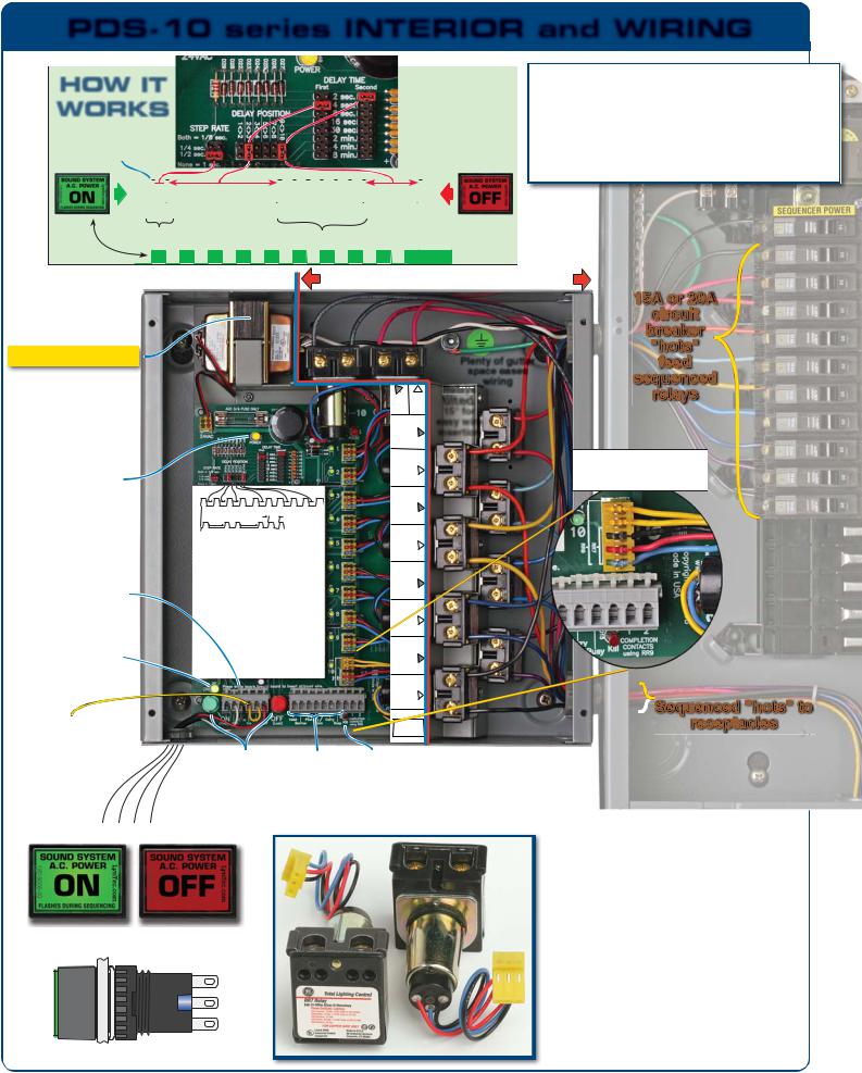
LynTec PDS-10 Brochure

low voltage lighting control relay Off 66% - www.gmcanantnag.net
Lighting & Electrical > Light Control Systems > Light Control ...

low voltage relay light switch Off 75% - www.gmcanantnag.net
Free Pdf Download » Search Results » Latching Relay Pdf

Modernize Vintage GE 24v Lighting Control System? - Projects ...

Modernize Vintage GE 24v Lighting Control System? - Projects ...
Low Voltage Relays in Lighting Systems Low Voltage relays ...

Kyle Switch Plates: New Replacement Parts for Residential GE ...
LIGHTING CONTROLS
GE Lighting Low Voltage Transformer 115V 277V

PDS-10 | Power Delay Sequenser | LynTec | AV-iQ

35 Unique Ge Rr7 Relay Wiring Diagram | Relay, Electromagnet ...

Greengate PSG FWB | PDF | Switch | Relay
A remote control apparatus - Patent 0323919
Lighting & Electrical > Light Control Systems > Light Control ...
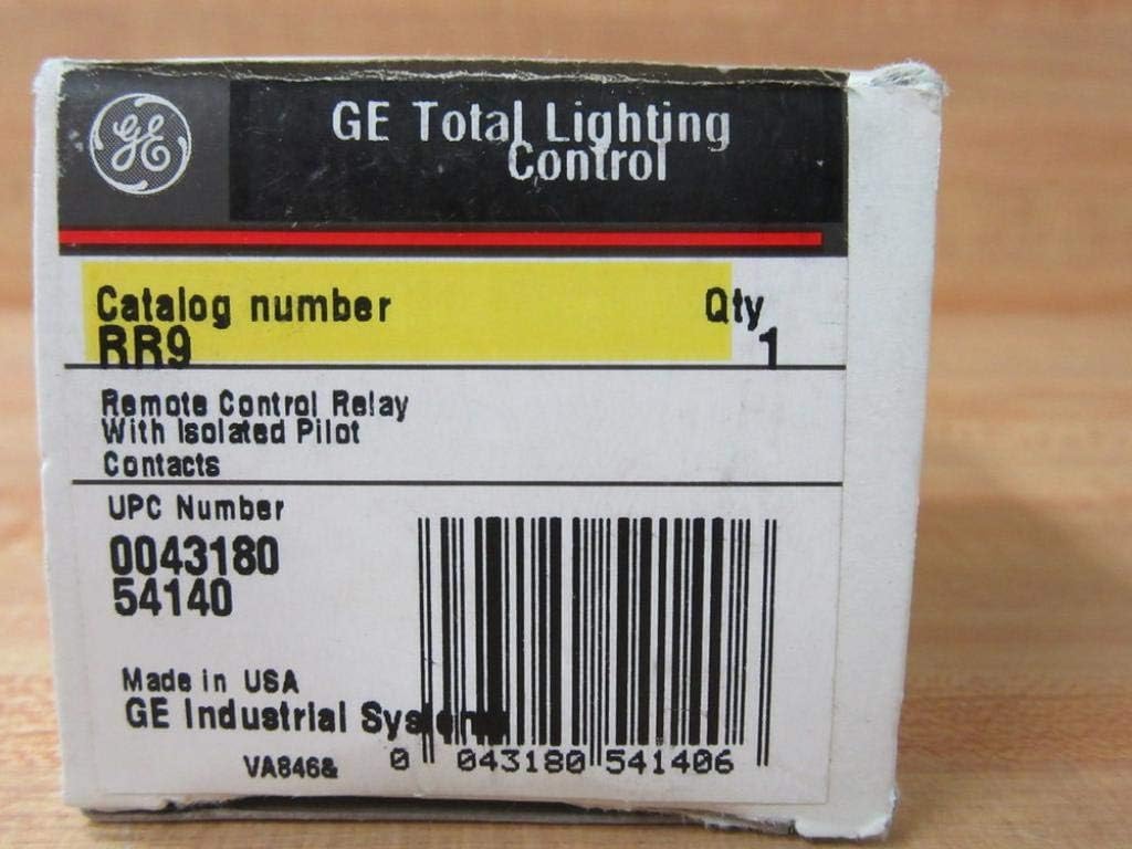
Amazon.com: 1- GE RR9 20A SPST Low Voltage Relay PILOT ...
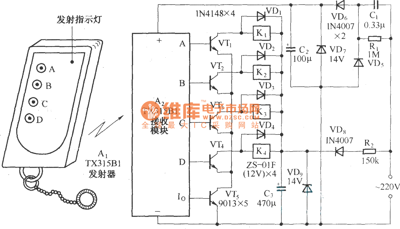
Four way remote control AC switching circuit diagram ...
0 Response to "38 ge rr7 relay wiring diagram"
Post a Comment