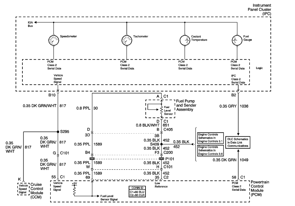
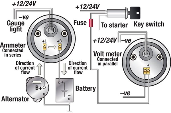
38 marine fuel sending unit wiring diagram
PDF KUS Electric Sending Unit Installation Guide WARNING ... Connect (black) wire. from the KUS sending unit to gauge hook-up. If your gauge has color coded hook-ups, maintain this coding as you connect the sender and ground wires. WARNING!! GASOLINE IS EXTREMELY FLAMMABLE. KEEP TANK AREA FREE FROM SPARKS AND FLAMES. EMPTY THE TANKS OF FUEL & FUMES BEFORE CONTINUING WITH INSTALLATION. Boat Fuel Gauge Not Working | Boating Mag A jumper wire fitted with alligator clips is a cheap and effective troubleshooting tool. So is a screwdriver. Boating Magazine. Boat fuel gauges can be troublesome. Here is a quick method of determining whether the fault lies in your boat's fuel gauge or in the fuel gauge sending unit on the tank.
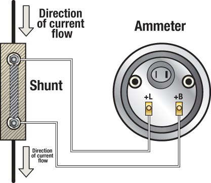
Honda Outboard Gauge Wiring Diagram - Wiring Diagram and ... Help Wiring Gauges The Hull Truth Boating And Fishing Forum. Honda marine bf135 wiring diagram pdf outboard engine tacklereviewer motor cable harness cruisers sailing instrument made easy what protocol for pair of digital 2008 ning buzzer mystery calling all yamaha multifunction gauges bf9 9 babl 1000001 1199999 owners mercury diagrams trim gauge the hull truth fuel and sending unit 1985 ...
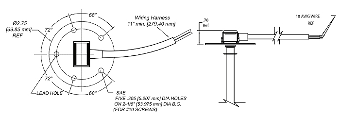
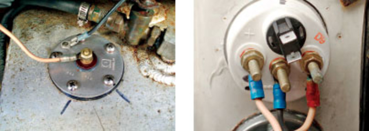
Marine fuel sending unit wiring diagram
PDF FUEL LEVEL SENDER - Livorsi Marine, Inc. 3) SEND and NEG wires reversed on Sending Unit. 4) Meter not grounded properly. 5) SEND wire is touching NEG terminal or wiring 6) Center rod on fuel units touching the outside tube. 7) Unit not calibrated. Water tank only: End of tube not sealed properly. WATER TANK SENDERS 1. The water tank units are not interchangeable with the fuel units. 2. How to Install a Level Sending Unit | KUS USA 1) Connect ground (pink) wire from the KUS sending unit to a common grounding hook-up. 2) Connect (black) wire from the KUS sending unit to gauge hook-up. If your gauge has color coded hook-ups, maintain this coding as you connect the sender and ground wires. Step 10 Turn on the power to the level sending unit and gauge. Wema Fuel Sender Wiring Diagram Diagram B I. Measure the depth of your fuel tank. Locate this dimension in Column "A" of Table 1. Column "B" shows the length from the underside. PROPER WIRING INSTALLATION: Connect ground (pink) wire from the WEMA sending unit to a common grounding hook-up. -Connect (black) wire from the WEMA sending unit to gauge hook-up.
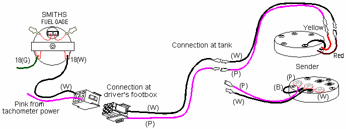
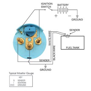
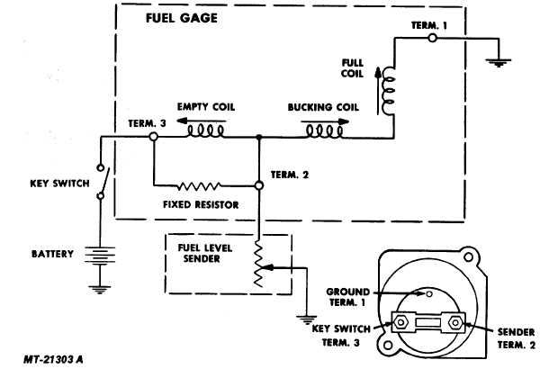
Marine fuel sending unit wiring diagram. How to Test and Replace your Fuel Gauge and Sending Unit ... Check the wiring diagram that comes with the kit and mark the back of the new fuel gauge with symbols for each post: "S" for the sender, "G" or "—" for the ground, and "I" for the ignition. Install the new gauge, reconnect the wiring and turn on the power. The fuel gauge should now show the correct fuel level in the tank. Moeller Fuel Gauge Wiring Diagram Moeller Gauge-Wiring Diagram 4″″ Universal Electric Fuel Sender Instructions Electric Fuel . Gauge pointer should be at the position shown in the lower portion of the diagram. To test senders, the resistance values are shown at minimum and full gauge scales. Fuel Systems (Marine) Voltage - "I" to "G" terminal - 10 to 16 volts. 52 results Gas tank sending unit wiring diagram help | Boating Forum ... 1. with key on, bridge or connect center wire on tank (usually pink) to the tank ground wire. If the tank has a spade connector, make sure its clean and tight. a. if Gage pegs to full, problem is in the sender in the tank (most likely) b. if gage does not move, ground the tank to the negative battery terminal and see if the gage pegs. Fuel Tank Sending Unit Wiring | Boating Forum - iboats ... The "S" wire from the gauge gets connected to the threaded post on the sender at the tank. The tab is the ground for the sender and it goes to the negative terminal of the battery or to the engine block. A second ground wire should run up to the filler port for the tank. The sender itself does not have +12 volts on it. Here is a diagram.
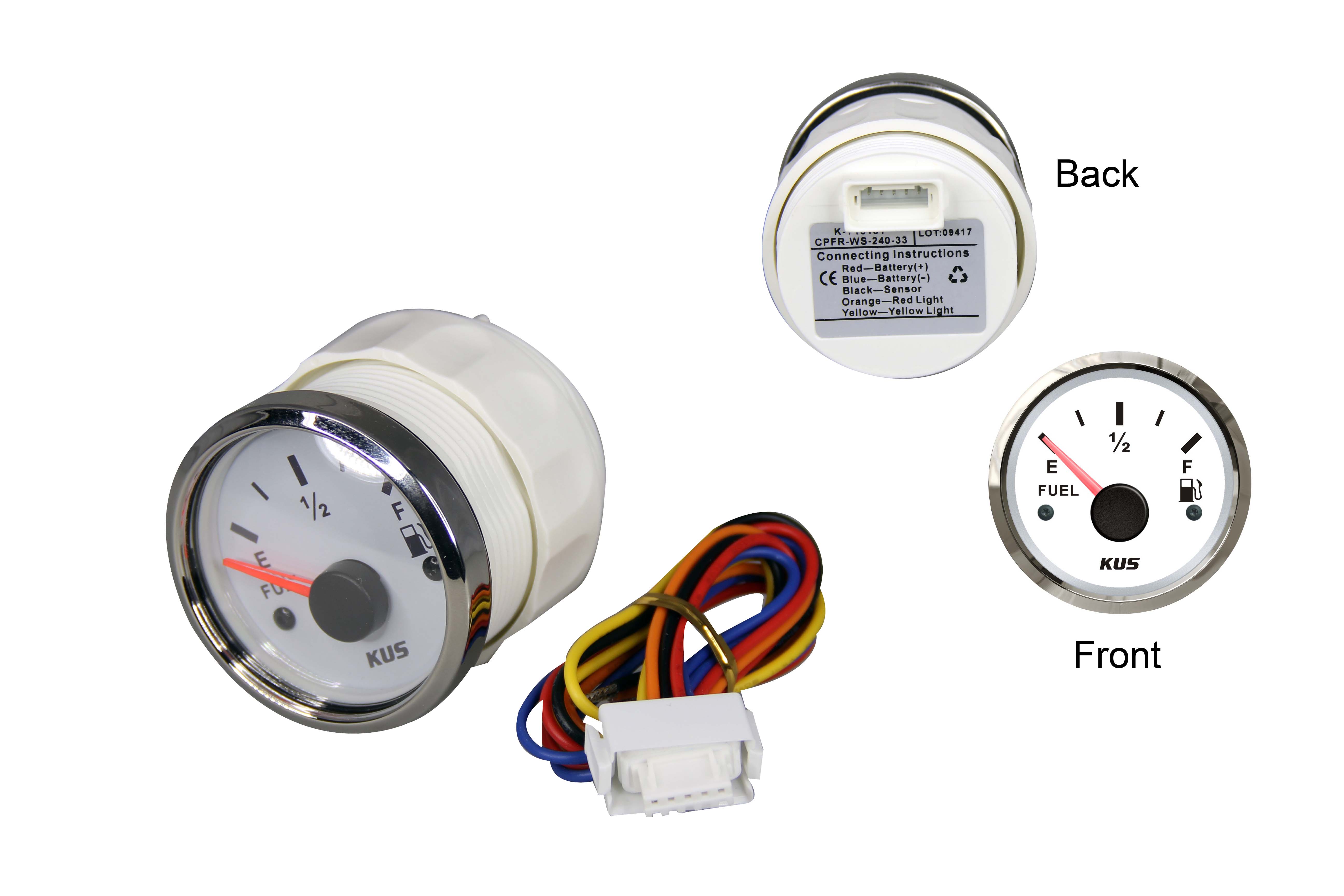
How to install a Moeller fuel gauge - Jamestown Distributors Install your electric fuel sender, gently inserting float arm into tank followed by sending unit. Align screw holes between gasket, mounting plate and tank. Secure sending unit to tank, tightening mounting screws into place just until white sealant shows beneath the screw head. DO NOT OVER-TIGHTEN. Fuel Gauge And Fuel Sending Unit Wiring Diagram - Fixya Make the connection near the fuel tank sending unit. Connect the alligator clip on the test lamp to a known GOOD ground. The bulb in the lamp should glow dimly. The dash gauge should read somewhere between 1/4 to 3/4 of a tank of gas. (Varies with make and model) This will verify that the gauge is either good or bad. Aug 09, 2008 • 1993 Saturn SL1 PDF SmartCraft Fuel/Paddle/Oil Boat Harness IMPORTANT: Sending units must be grounded to the engine battery negative terminal for the sending unit to function. 4. Connect the wire harness lead flagged "FUEL 1" to the main fuel tank sender, if equipped. 5. Connect the wire harness lead flagged "FUEL 2 / OTHER" to the water separating fuel filter sender, if equipped. Kus Fuel Gauge Wiring Diagram - schematron.org run wiring from gauge to fuel cell. Connect the Black wire from the Probe to the "G" or Ground terminal on your gauge. Connect the Red wire to the "S" or Sender terminal on your gauge. Connect the yellow wire to the Gold terminal on the Low Level LED Lamp and connect the silver terminal on the lamp to Ground. Connect the "I. wiring instructions.
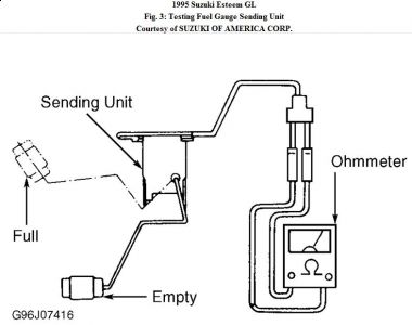
Fuel Tank Sending Units - Marine Parts Source Maintain a high-performing fuel system with a quality marine fuel tank sending unit. Shop top brands like Moeller Marine, VDO & Wema USA. Ships same day! How to wire up a fuel sending unit? - JustAnswer The fuel tank should be grounded and the sender wire pink should be connected to the sender terminal on the sending unit this is the correct wiring. The sending unit will ground through the mount screws. The fuel gauge reads the resistance to ground check the wires on the back of the gauge pink to S terminal and black to G terminal. PDF Electric Sending Unit - Seachoice to the fuel tank to the connection of the dash mounted gauge. 3. Be sure the sending unit floats moves freely. If none of these suggestions help, remove the tank sending unit. Run a jumper wire from the gauge mounting flange on the tank to sending unit's flange. Move the float up and down to see if the 240 to 33 ohm range work on dash gauge. 1. How to Wire a Fuel Sending Unit - It Still Runs Step 2 Cut two equal lengths of wire. One should be long enough to reach the back of the fuel gauge, and the other to the nearest ground connection. Strip about a centimeter from the ends of both of these wires, and twist the strands together. Step 3 Loosen the screws for the ground and ignition connections on the sending unit.
PDF Gauge and Sending Unit Wiring Diagram and ... - Moeller Marine Gauge and Sending Unit Wiring Diagram and Industry Recommendations. IGNTION SWITCH BLACK BULB SENDER GRND SENDER BATTERY GROUND FUEL . Recommended Marine Wiring Color Code Direct Current Systems - Under 50 Volts (No diagram required if wiring is in compliance with Tables I and Il) Color Yellow w/Red Stripe (YR) Yellow (Y) Dark Gray (Gy) Brown (Br)
marine fuel gauge wiring diagram - Wiring Diagram and ... How To Wire Up A Fuel Sending Unit 2 12v Fuel Level Gauge Resistance 240 33 Ohm 24v Rv Universal Oil Meter E 1 F Indicating Range Lighting Background Anti Fogging Rust Waterproof Stainless Stress Frame For Boat Marine Online In Turkey Engine Instrument Wiring Made Easy Boats Com
Wiring Diagram For A Boat Fuel Gauge - Wiring Diagram Line Wiring Schematic For Fuel Gauge On Nonsuch 30 Cruisers Sailing Forums Installation Troubleshooting Boat Gauges Instrumenteters Boatus 2 12v Fuel Level Gauge Resistance 240 33 Ohm 24v Rv Universal Oil Meter E 1 F Indicating Range Lighting Background Anti Fogging Rust Waterproof Stainless Stress Frame For Boat Marine Online In Turkey
Bass Tracker Boat Wiring Diagram - Wiring Diagram and ... Pro 170 Tracker Mod V Bass Boat. Tracker boats wiring diagram boat building standards basic trailer tacklereviewer 1985 bass with 150 merc the diagrams page 2 10 rules for a upgrading 175 electronics how to wire jon ignition switch troubleshooting fuse panel this old 2019 pro team txw mod v beginners guide livewell timer installation archive electrical systems 170 makeover step by 1974 mercury ...
Tracker Pro Guide V16 Boat Fuel Gauge Wiring Diagram Fuel guage does not work, registers empty (full tank of fuel). Checked the ohms on the sending unit for resistence and it seems to work properly. Jumped the gauge and it and the gauge went over to the full mark. Direct wired the sending unit to the gauge with new wire and still nothing. ... Yellow_zq8 on Tracker pro guide v16 boat fuel gauge ...
Wema Fuel Sender Wiring Diagram Diagram B I. Measure the depth of your fuel tank. Locate this dimension in Column "A" of Table 1. Column "B" shows the length from the underside. PROPER WIRING INSTALLATION: Connect ground (pink) wire from the WEMA sending unit to a common grounding hook-up. -Connect (black) wire from the WEMA sending unit to gauge hook-up.
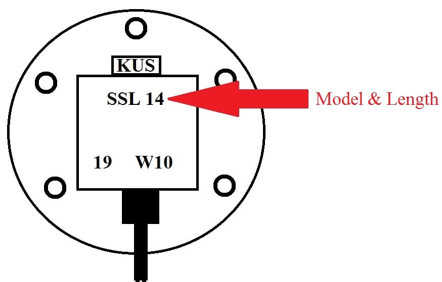
How to Install a Level Sending Unit | KUS USA 1) Connect ground (pink) wire from the KUS sending unit to a common grounding hook-up. 2) Connect (black) wire from the KUS sending unit to gauge hook-up. If your gauge has color coded hook-ups, maintain this coding as you connect the sender and ground wires. Step 10 Turn on the power to the level sending unit and gauge.
PDF FUEL LEVEL SENDER - Livorsi Marine, Inc. 3) SEND and NEG wires reversed on Sending Unit. 4) Meter not grounded properly. 5) SEND wire is touching NEG terminal or wiring 6) Center rod on fuel units touching the outside tube. 7) Unit not calibrated. Water tank only: End of tube not sealed properly. WATER TANK SENDERS 1. The water tank units are not interchangeable with the fuel units. 2.
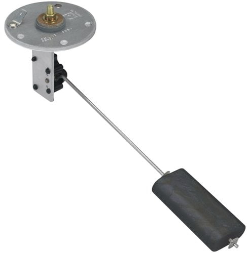
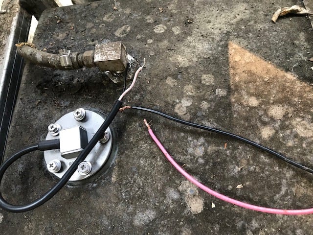









0 Response to "38 marine fuel sending unit wiring diagram"
Post a Comment