7 mechanically held contactor wiring diagram
The C30CN 30A mechanically held lighting contactors from are designed for industrial, commercial and outdoor lighting applications where efficient control is required. the coil for contactor operation. CR463M Mechanically Held Contactors A mechanical latch with a 2- or 3-wire electronic control module delivers reliable performance and protection from such application abnormalities as line noise, leakage currents from controller outputs, or short repetitive commands burst from faulty controllers. Mechanical ...
Diversified power management company and global technology leader in electrical systems for power quality, distribution and control; hydraulics components, systems and services for industrial and mobile equipment; aerospace fuel, hydraulics and pneumatic systems for commercial and military ...
Mechanically held contactor wiring diagram
Access Product and Software Documentation, explore Product and Service Content organized by Industry, learn about Services, Training and Technical Support, read about our Capabilities and Engineering Expertise Electrically Held to Mechanical Latch Contactor • Retrofit Instructions 5 1502-IN001%-EN-P – -XQH Install the Mechanically Latched Auxiliary Contact Assembly 1. Wire the closing and trip coils to the Mechanically Latched auxiliary contact assembly as shown in the diagram below: Figure 6 – Auxiliary Contact Assembly Layout 2. ASCO 918 Lighting Contactors Drawing & Wiring Diagrams Drawing and Wiring Diagrams Typical wiring diagrams for Standard and accessory control situations Standard Wiring Accessory 47 Two Wire Control. Accessory 48 Three Wire Control! Accessory 49 Stop/Start Control ! RC CONTROL CONIRCL MCDU1f CON 1 Rot . c.cWROL CONTROL MODULE
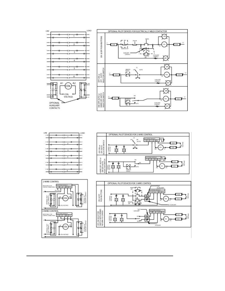
Mechanically held contactor wiring diagram. May 15, 2018 - Issue: Wiring a 3-wire Photocell ... Lighting contactor Environment: 8903 Type L electrically held Resolution: Most standard photocells have 3 wires. Black is supply voltage, L1. White is neutral or L2. Red is the switched leg. Run the switched leg to one side of the coil and the other side of the coil to the neutral or L2. See attached diagram... Ge Lighting Contactor Cr460 Wiring Diagram. GE CR Series Lighting Contactors Contact position indication - when button protrudes, two #8 AWG wires A simple kit easily converts electrically held units to mechanically held and . FIELD WIRING DIAGRAM VAC THREE PHASE . GE's new CR Series lighting contactors deliver unprecedented versatility in .. table c: 3-wire connection diagram c electronic p1 p2 a1 p3 p4 module p5 a2 control voltage n p p coil n voltage 3 3 p1 p2 p3 p4 p5 electronic module c a2 a1 c fuse 2 fuse coil voltage 2 off g on r cc p n off on p1 p2 p3 p4 p5 a1 c fuse coil voltage 2 cc p hand off auto table b: optional wiring and pilot devices for mechanically-held contactor, 2-wire control off-on off-auto selector switch Sep 13, 2021 · Mechanically held lighting contactor wiring diagram. Here is a picture gallery about mechanically held lighting contactor wiring diagram complete with the description of the image please find the image you need. The wa4 mechanical latching unit for af tactors can be easily converted into compact latched contactors.
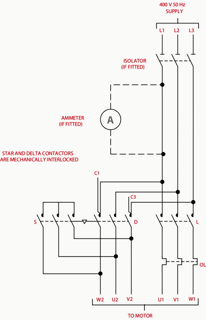
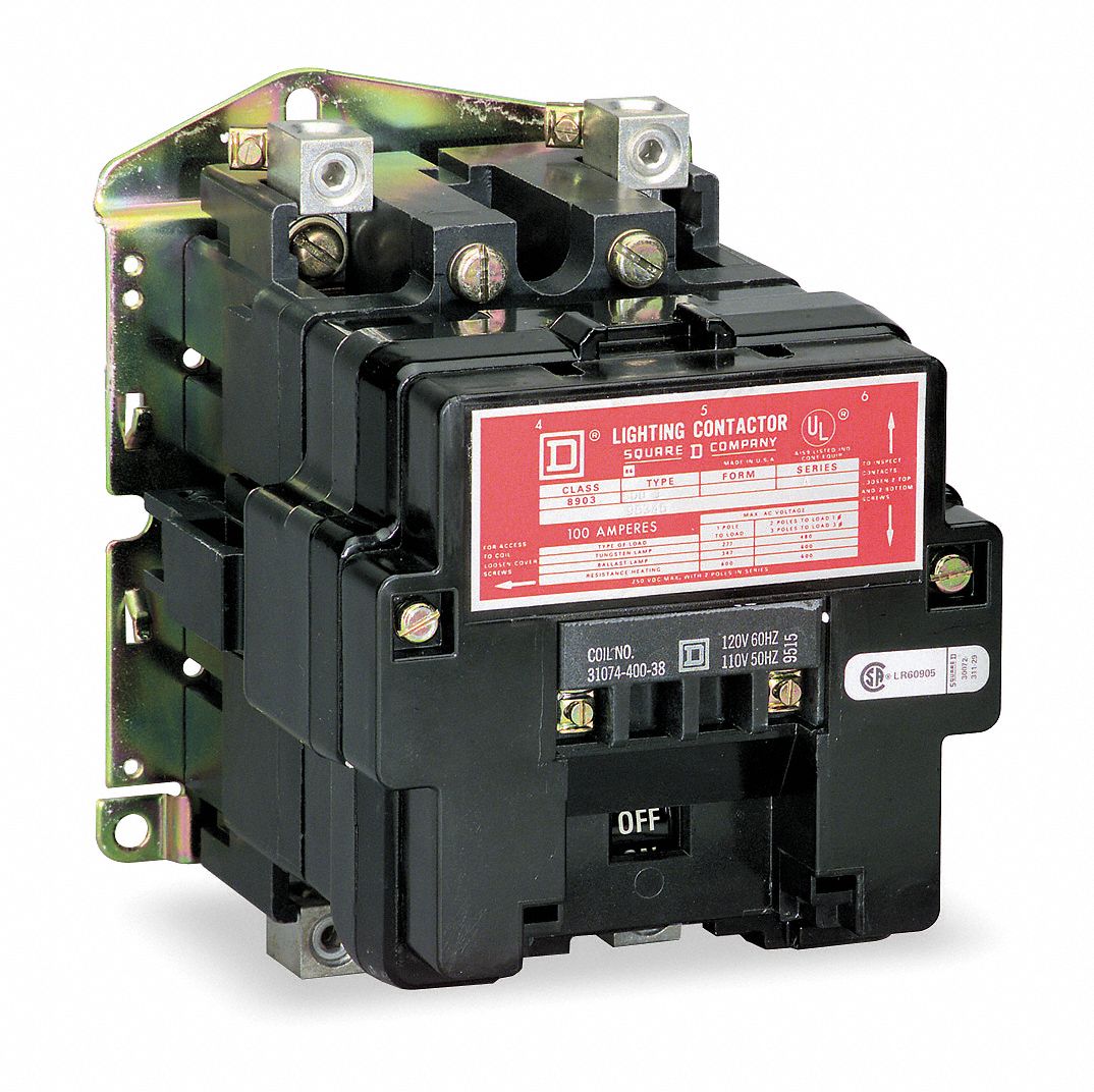
Joslyn Clark's unique Compact AC Vacuum Contactors & Starters are ideal for tough industrial applications. The compact design pro- ... • Mechanically Interlocked Version available for reversing application ... WIRING DIAGRAM START STOP SEPARATE AC SOURCE SCHEMATIC T1 T3 L2 T2 T2 T3 L3 Dec 10, 2017 · Wiring Diagram Book Schneider Electric. Instruction Bulletin Schneider Electric. Contactorotor Starters. Square D 8903spo11v02 110 120 Vac 60 Amp 3 Pole Open Type Mechanically Held Lighting Contactor Cooper Electric. Selecting Effective Lighting Control White Paper. Square D 8903lo20v02 Province Electric Supply. C30CN = Open 30A lighting contactor Class E = Electrically held M = Mechanically held Mechanically Held Control Module Voltage A0 = 110–120 Vac H0 = 200–277 Vac T0 = 24 Vac T1 = 24 Vdc Number of Normally Closed Poles 0–8 Sample Catalog Number: Digit Position: C 3 0 C N M 2 2 A A 2 A 0 123456789 10111213 Control Module Operation 2 = Two ... Feb 16, 2019 · Variety of mechanically held lighting contactor wiring diagram. A wiring diagram is a simplified standard pictorial depiction of an electric circuit. It shows the elements of the circuit as simplified forms, as well as the power and also signal connections in between the gadgets. A wiring diagram normally offers details regarding the relative setting and setup of tools as well as terminals on the tools, to aid in structure or servicing the device.
Mechanically Held 30 Ampere Lighting Contactors Application Guide AP03702001E Effective February 2006 ... FIGURE 5.Ê3-WIRE CONTROL WIRING — ONE SOURCE Triac Coil Contactor Operates Control Command Micro- Controller 60 ms Pulse Auxiliaries Change State Latch Activated NO/NC Auxiliary Contact m A1 A2 24, 120 or 277 Vac 50/60 Hz P2 P3 P4 P5 P1 ... Ge Lighting Contactor Cr460 Wiring Diagram wiring diagram is a simplified pleasing pictorial representation of an electrical circuit. Wiring Diagram For Contactor Lighting. New General Electric Ge Cr460b Cr463l50ana 5 Pole 277 Volt Lighting Contactor. GE CR Series Lighting Contactors Contact position indication when button protrudes. Feb 03, 2019 · Mechanically held lighting contactor wiring diagram. Class lc electrically held lighting contactors convertible to mechanically held features 8 catalog numbering system 9 selection 10 11 technical data 12 accessories factory mods and replacement parts 13 16 dimensions 17 21 wiring diagrams 22 24 contents class clm mechanically held lighting contactors are. 14 Nov 2004 — I am looking for help or possibly a diagram on how to connect a mechanically held lighting contactor to a photocell.
Selecting effective lighting control
Shop for mechanically held lighting contactor from Platt Electric Supply
Contactor As An Important Part Of The Motor Control Gear | EEP
November 18, 2017 - Issue:How to tell whether lighting contactor is mechaniclly held or electrically heldProduct Line:8903 Lighting ontactorsEnvironment:Products sold and used in the United…
Configuring Class 8903 L/LX Lighting Contactors Normally Open/Closed | Schneider Electric Support
Mechanically Held Contactor Wiring Diagram is good choice for you that looking for nice reading experience. We hope you glad to visit our website. Please read our description and our privacy and policy page.

Pin on Motor 3 fase
Access Product and Software Documentation, explore Product and Service Content organized by Industry, learn about Services, Training and Technical Support, read about our Capabilities and Engineering Expertise

GE 463MD0CJD Lighting Contactor Mechanically Held 30A NEW ...
Wiring Terminals. Class Type S multipole lighting contactors are available as electrically held or mechanically held devices and can be ordered as Schneider Eletric Square D Picture Wiring Diagram Book, 7/14/18, English, CTpdf MB. Class / Refer to Catalog CT Square D panelboards; short- circuit ratings to kA; Table Class Type PB Lighting ...

Contactors and Motor Starters
Abb Cr460xmn Lighting Contactor Conversion Kit Electrically Mechanically Held Rexel Usa. Ge Lighting Magnetic Contactor 120v Ac Coil Volts Type Electrically Held Number Of Poles 3hya1 Cr463l40aja Grainger. Ge Cr460xp32 2 Pole Power For Cr460 Series Lighting Contactor Newegg Com.

Tech Tip: How To Setup and Use Latching Contactors
FEEDBACK loop from NC auxiliary contact ensures proper coordination between contactor status and control command. FIGURE 3. 2-WIRE CONTROL WIRING — TWO SOURCES.
Introduction Contactor Components
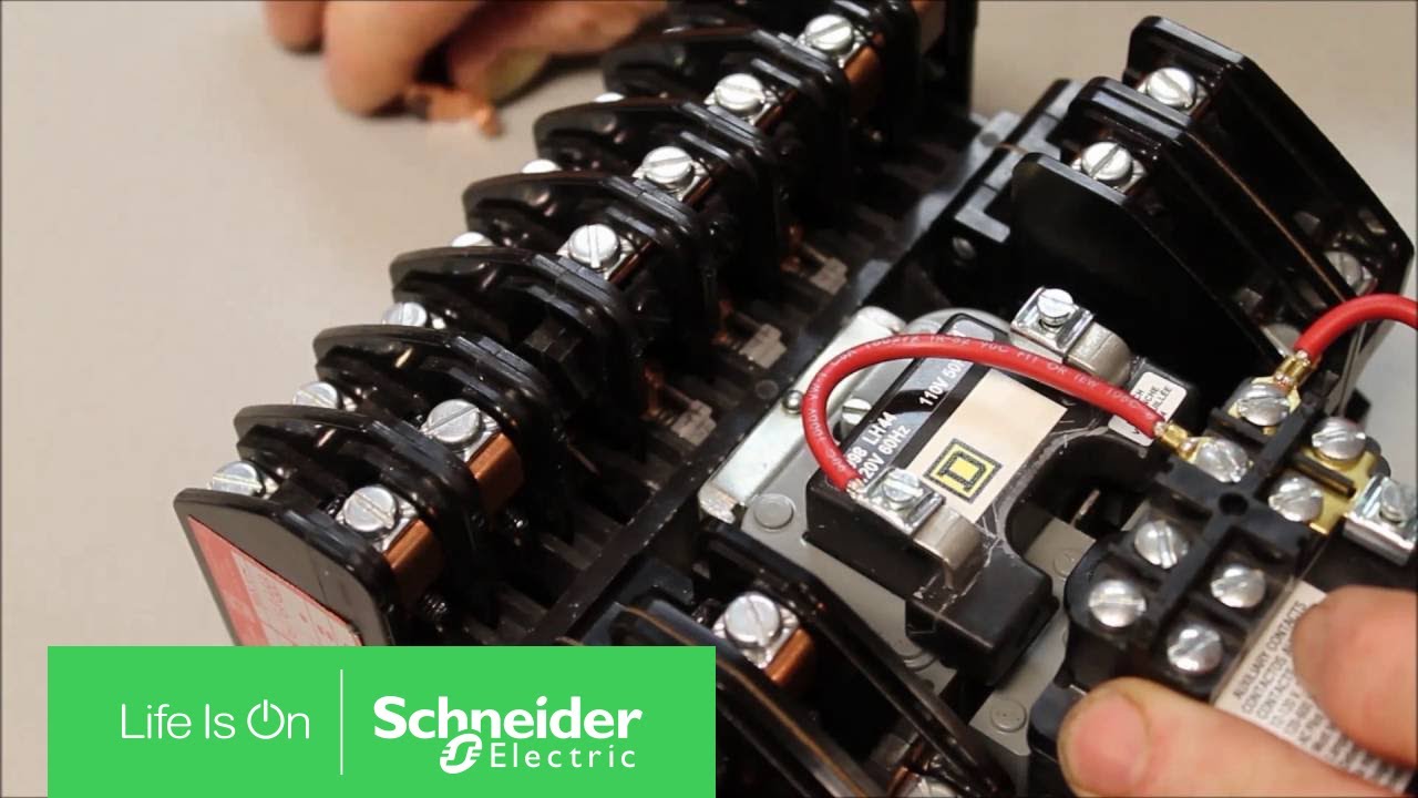
How to assemble a mechanically interlocked and reversing contactor. Buy the items in this video at 800-337-1720 or go to: http://www.galco.com/scripts/cgiip....

Contactors and Motor Starters
June 8, 2016 - Is there a mechanically held contactor out there that I can control like an electrically held one? I know the GE/Eaton plastic ones with the addition of an accessory, can be controlled like an electrically held one, ie two wire. Power to the coil and contactor closes, removal of power to coil...

ABB CR460XMN :: Lighting Contactor, Conversion Kit ...
Square D Wiring Diagrams For Contactors Starters Relays And Controllers Catalog Schneider Electric Usa. Square D No Enclosure 4 Pole Mechanically Held Lighting Contactor 72603871 Msc Supply. Square D Lighting Magnetic Contactor 120v Ac Coil Volts Type Electrically Held Number Of Poles 2cg65 8903lo40v02 Grainger.
Bul 500LG Lighting Contactor (Mechanically and Electrically Held)
Frost Supply is the place to shop for Lighting Contactors Mechanically Held

SQUARE D 8903LXO0012V02 : LIGHTING CONTACTOR 600VAC 30A LX
Ge lighting contactor cr460 wiring diagram. Ge lighting contactor cr460 wiring diagram ge control catalog section 3 74951. Here is a picture gallery about mechanically held lighting contactor wiring diagram complete with the description of the image please find the image you need. Many large pieces of. Source: hanenhuusholli.blogspot.com

Contactors (Control Pilot Devices)
Dec 10, 2017 · Wiring Diagram For Mechanically Held Contactor. Cr460 series revision 11 021402 c30cn lighting contactors instruction sheet contactorotor starters if 1698 xlc explosionproof i have a master electrician working on my house but he has never installed mechanically held square d 8903 lx ge solutions contactor user manual page 4 class type 2 thru 12 ...
Selecting Effective Lighting Control White Paper
May 2, 2018 - Issue: What is the difference between electrically held and mechanically held lighting contactors? Product Line: NEMA Lighting Contactors Environment: Products sold and used in the United States Cause: Selecting mechanically versus electrically held lighting contactors Resolution: Electrically ...
GE Industrial Solutions CR460 LIGHTING CONTACTOR SERIES User ...
3-16 Modified assembled forms - electrically held 3-18 Lighting contactors CR463M 3-18 Standard assembled forms 3-20 Modified assembled forms - mechanically held 3-22 Lighting contactors CR460, CR463 3-22 Technical data 3-23 Lighting contactors CR463L, CR463M 3-23 Wiring diagrams 3-24 Outlines and dimensions for estimating only
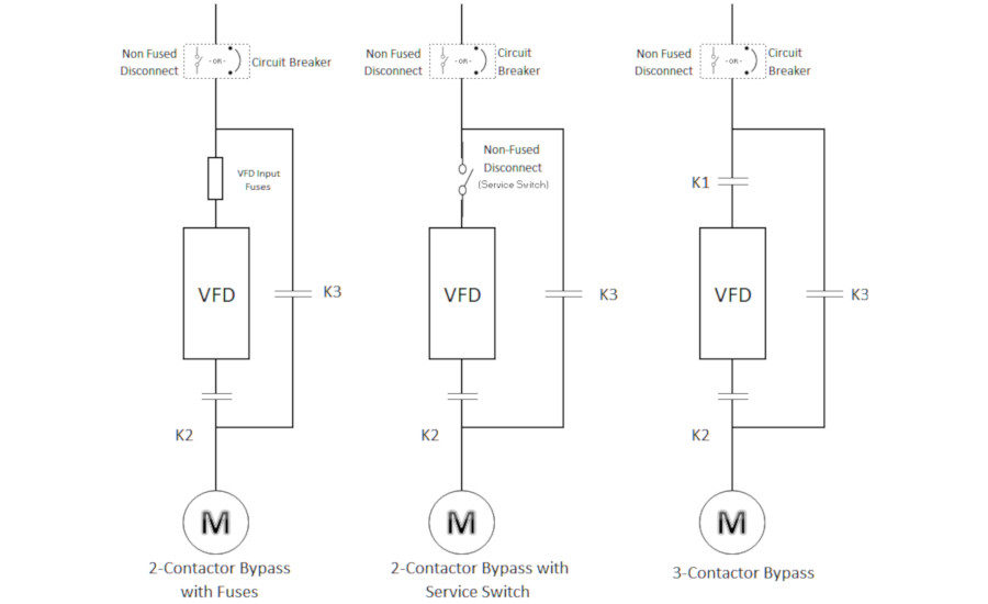
In HVAC VFDs, Is 2-Contactor Bypass Really Better than 3 ...
14.01.2019. 14.01.2019. 3 Comments. on Ge Lighting Contactor Cr460b Wiring Diagram. Results 1 - 48 of 90 NNB GE CRB Lighting Contactor 12 Pole w/v Coil .. There is a k.o. in the front cover for 1 device and wiring diagrams inside the. GE Industrial Solutions CR LIGHTING CONTACTOR SERIES User Manual. Page 4 Wiring Diagrams CRM Mechanically Held ...
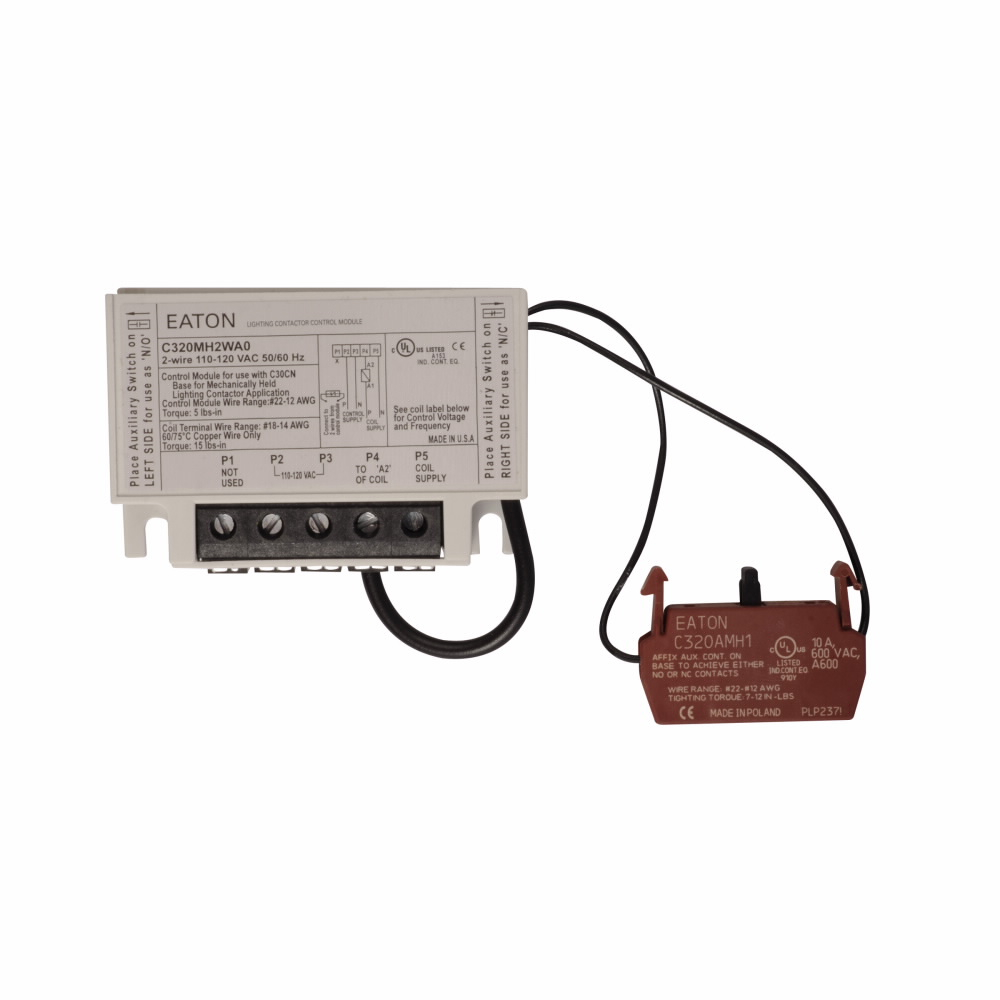
Eaton Cutler Hammer, C320MH2WA0, 30A Mech Held Module Kit 2-wire 120V AC
contactor is operated from a momentary pilot device and requires an auxiliary contact tobe used as a holding interlock. • 2-wire control is used for single location control with power continuously supplied to thecoil for contactor operation. CR463M Mechanically Held Contactors
CR460 series Revision 11 021402
To find your nearest Summit Service Center, click here.https://www.summit.com/locations
C30CN lighting contactors instruction sheet
Shop Electrical Supplies Online at Crescent Electric Supply Company. Serving the electrical, construction, commercial, industrial, utility and datacomm markets.
Volume 10 Tab 4
Wiring Diagram (Electrically Held Contactor) Refer to control module instruction sheets for wiring of mechanically held contactors. Class LC Electrically Held Lighting Contactor (Convertible to Mechanically Held) Catalog numbers LCE00C* Page 5 of 6 Notes: 1. Refer to the NEC or local electric code as required. 2.

Contactor - Wikipedia
Len00b004120b Lighting Contactor Siemens In Stock Santa Clara Systems. Wiring a contactor with an mcb and rccd shower question r uk emergency test switch installation hager diagram what relay to use d i y kit uk420 flip flop lighting system wired have master electrician working on lc series contactors lc100r t british general fortress 20a dp is there single phase for ac3 917 918 remote help ...
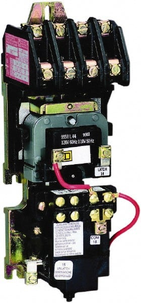
Lighting Magnetic Contactor, 120V AC Coil Volts, Contactor Type: Mechanically Held, Number of Poles:
Class Type S multipole lighting contactors are available as electrically held or mechanically held devices and can be ordered as Schneider Eletric Square D Picture Wiring Diagram Book, 7/14/18, English, CTpdf MB. I have a LXG lighting contactor and need the wiring diagram for this. where do i go to get this? I can get my - Square D 30 Amp Lighting.
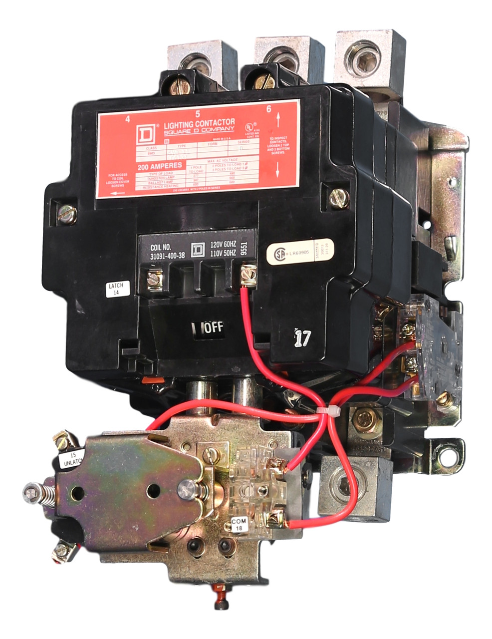
8903SVO11V02 Open Lighting Contactor 200A Square D 120V Coil
Conversion kits for mechanically held contactors Kits for converting an electrically held contactor to a mechanically held version. Kits includes control module, latch, latch cover and auxiliary contact(s) plus installation instructions. Conversion kits are suitable for coil voltages 277 V and below. Use CPT to reduce coil voltage if line voltage
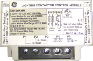
GE CR460XMN - 3-Wire 110-120VAC Conversion Kit for Mechanically Held Contactors
Square D Lighting Contactor Wiring Diagram. mechanically-held contactor, 2-wire control off-on off-auto selector switch hand-off-auto on-off-auto selector switch control voltage control voltage (right aux.) 8903 sv02 square d wiring diagram for mechanically held lighting contactor unique.
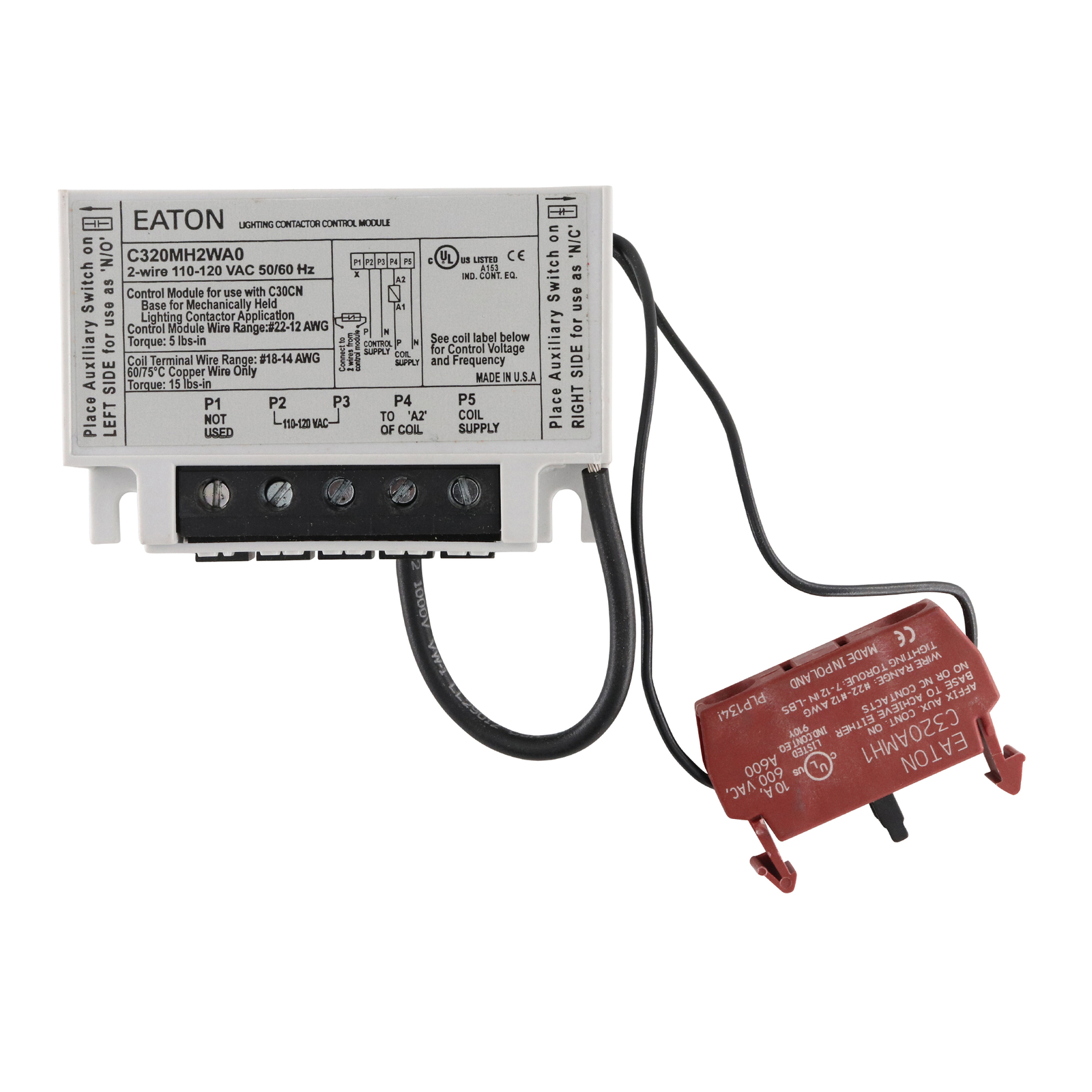
Eaton C320MH2WA0 2-wire Mechanically Held Module Kit for sale ...
May 11, 2012 - There is a two wire conversion kit that will convert it to "electrically held", but you will need a 24 hour hot for the control module to work. Otherwise, you will have to change the coil out to the one used in the regular electrically held contactor. ... its an Eaton C30CNE with a 320MH2WAO mechanical ...
Square D - No Enclosure, 4 Pole, Mechanically Held Lighting ...
From departure to destination, and every leg of the journey in between, we're working to get you there safely, reliably and efficiently. Because that's #WhatMatters. See how: https://eaton.works/2SiQtVX

CR460 Series | ABB US
electrically held contactors require a constant current and a constant power dissipation to hold the circuit. a common relay or motor starter is a good example of this type of contactor. a mechanically held contactor is held in place without the need of a constant power drain. the coil on these type of contactors is far less likely to burn up ...
Lighting contactors
Lighting Contactor Schematic - 9 images - lighting circuits connections for interior electrical, photocell light switch wiring diagram electrical circuit,

Class 8903 Type LX Mechanically Held Lighting Contactor 2 ...
Eaton contactor wiring diagram lovely wiring diagram contactor. Mechanically held lighting contactors from eatons electrical sector are designed for industrial commercial and outdoor lighting applications where efficient control is required. Switch it off from the systems circuit breaker.
Electrically & Mechanically Held Multi-Pole Lighting ...
Non-combination C30CN Electrically and Mechanically Held ... Wiring Diagrams . ... Class ECC04 — Non-combination Mechanically Held Lighting Contactor ...

SOLVED: I have a 8903 LXG lighting contactor and need the - Fixya
ASCO 918 Lighting Contactors Drawing & Wiring Diagrams Drawing and Wiring Diagrams Typical wiring diagrams for Standard and accessory control situations Standard Wiring Accessory 47 Two Wire Control. Accessory 48 Three Wire Control! Accessory 49 Stop/Start Control ! RC CONTROL CONIRCL MCDU1f CON 1 Rot . c.cWROL CONTROL MODULE

Eaton IF 1698 - XLC Explosionproof Lighting Contactors ...
Electrically Held to Mechanical Latch Contactor • Retrofit Instructions 5 1502-IN001%-EN-P – -XQH Install the Mechanically Latched Auxiliary Contact Assembly 1. Wire the closing and trip coils to the Mechanically Latched auxiliary contact assembly as shown in the diagram below: Figure 6 – Auxiliary Contact Assembly Layout 2.

C30CNM120A02A0-CHGP
Access Product and Software Documentation, explore Product and Service Content organized by Industry, learn about Services, Training and Technical Support, read about our Capabilities and Engineering Expertise
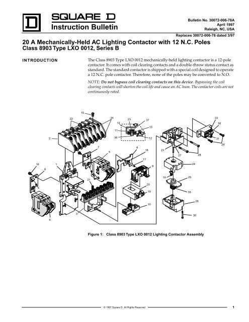
Instruction Bulletin - Schneider Electric
Has anyone wired this kind of lighting contactor with a ...
Selecting Effective Lighting Control White Paper

Class 8903 Type LX Mechanically Held Lighting Contactor 2 ...
0 Response to "7 mechanically held contactor wiring diagram"
Post a Comment